
If a jockey pump keeps running, first establish whether system pressure is still rising, remains below the stop point or has already reached the approved stopping condition. Those three observations separate a hydraulic problem from a controller or timing problem. Possible causes include water loss, an open test or drain path, reverse leakage, inadequate pump delivery, an incorrect sensed pressure or a command that remains active. Treat unexplained operation in a fire-protection system as a service issue requiring qualified personnel. Do not disable the main fire pump or alter protection settings to silence the symptom.
Confirm the operating condition before investigating
A pump that runs continuously is different from one that starts and stops repeatedly. Record both patterns accurately. Continuous running may mean that the pressure target is never reached; frequent starts may mean pressure is restored but quickly lost again. The same leak can contribute to either pattern depending on its size and the available pump delivery.
Start with the control position, displayed status, available event log and the time the condition began. Check for a known test, system refill, maintenance activity or genuine fire demand. Operators should follow the site’s emergency procedures when there is an alarm, abnormal pressure loss or an uncertain protection condition. Routine troubleshooting must not delay an emergency response.
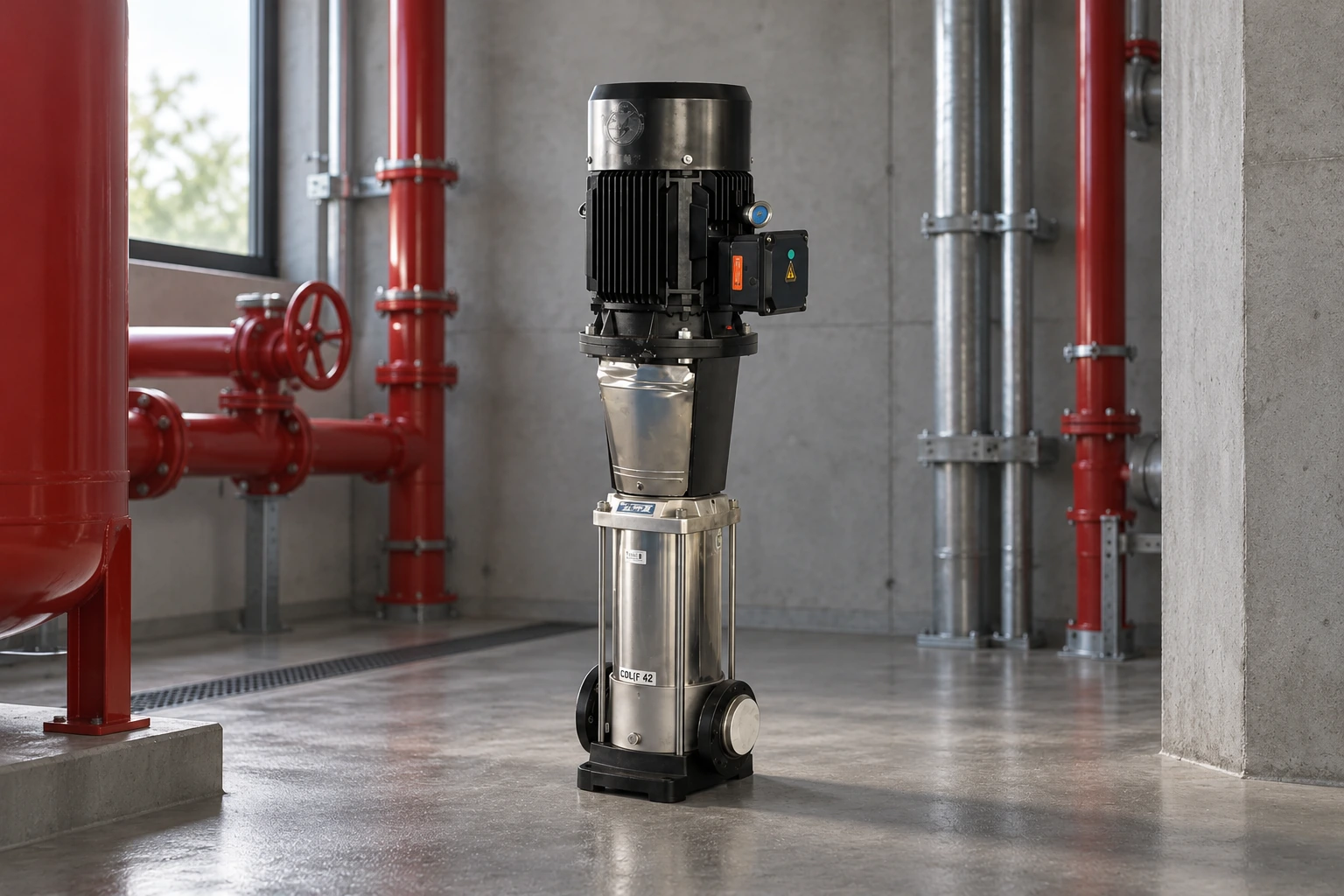
Borra’s CDL(F) vertical multistage jockey pump is relevant to pressure-maintenance applications. Its selection still needs the project duty, approved settings, actual controller and system arrangement. A product page or image cannot establish that a particular installation is correctly sized or ready for service.
Use pressure behavior to choose the next check
Observe pressure and elapsed time together. Compare the controller reading with a suitable test gauge where the approved procedure permits. Note the measuring locations: pump discharge pressure, system pressure beyond a check valve and a remote display can represent different points. A disagreement needs investigation before anyone changes a setting.
| Observed behavior | Giải thích có thể có | Bằng chứng cần thu thập |
|---|---|---|
| Pressure rises normally and the pump later stops | Expected recovery or an approved timing function | Original settings, event times and normal operating baseline |
| Pressure rises slowly but never reaches stop | Continued water loss or reduced available delivery | Suction and discharge observations, recent changes and leak investigation |
| Pressure remains nearly flat while running | Open flow path, supply restriction or pump problem | Authorized valve checks, supply condition and actual hydraulic measurements |
| Test gauge reaches stop pressure but display does not | Sensing path, instrument or location discrepancy | Gauge comparison and sensing arrangement review |
| Display reaches stop condition but motor continues | Active manual command, timing logic or control fault | Command status, timer state and controller specialist findings |
| Pressure falls promptly after a normal stop | Water escaping or returning through another path | Pressure-decay record and controlled investigation of check and drain paths |
These are investigation branches, not proof of a failed component. More than one condition can coexist. For example, a worn pump may recover a tight system but fail to keep up after a new leak develops. Preserve the observations before replacing parts or changing controls.
Check for water leaving through a known path
Review recent testing and maintenance first. A drain, test connection or other intentional outlet left open can create continuing demand. Look for visible discharge only from safe, accessible positions. Record the location and have authorized personnel compare the arrangement with the approved drawings and valve schedule.
Hidden leakage needs a controlled investigation. Underground piping, concealed connections and valve assemblies may lose water without leaving an obvious puddle in the pump room. A pressure log can show when the behavior changed, but it cannot locate the leak by itself. Correlate it with maintenance work, building events and the system’s normal baseline.
Do not close fire-system valves experimentally to “see what happens.” Isolation can impair protection and affect alarms or other buildings. Any sectional testing belongs under the facility’s approved impairment and restoration process. The person directing that work must know the affected area, notifications, alternative precautions and requirements for returning the system to service.
Consider reverse leakage without assuming it
A discharge check valve is intended to limit reverse flow, but a falling system pressure alone does not prove that it is leaking. Pressure can also leave through drains, system leakage or other connected equipment. Compare the documented piping arrangement with pressure behavior before assigning the cause to one valve.
An approved investigation may compare pressures across the relevant boundary, inspect accessible discharge evidence or examine a valve after proper isolation. Record orientation, identification and as-found condition. Avoid opening a pressurized line or touching moving equipment. Keep removed components and photographs if the finding needs supplier or engineering review.
Correct the cause rather than automatically fitting a larger jockey pump. Extra capacity may hide continuing water loss and change how the fire-protection sequence responds. Review the original design basis with the responsible fire-protection professional before any change in capacity or pressure capability.
Verify that the pump can restore pressure
Check the available source and accessible instrument readings. A suction restriction, loss of prime where applicable, air entry, incorrect rotation after electrical work or internal wear may reduce delivery. Motor operation proves that the motor is turning; it does not prove that the required water flow or differential pressure is available.
Use the installed pump’s curve and approved duty when interpreting performance. The relevant pressure relationship includes inlet conditions and losses through the connected path. Do not compare a single discharge reading directly with a nameplate without considering the source pressure, measuring location and actual operating condition.
The cURL Too many subrequests by single Worker invocation. To configure this limit, refer to https://developers.cloudflare.com/workers/wrangler/configuration/#limits cURL Too many subrequests by single Worker invocation. To configure this limit, refer to https://developers.cloudflare.com/workers/wrangler/configuration/#limits.
cURL Too many subrequests by single Worker invocation. To configure this limit, refer to https://developers.cloudflare.com/workers/wrangler/configuration/#limits
cURL Too many subrequests by single Worker invocation. To configure this limit, refer to https://developers.cloudflare.com/workers/wrangler/configuration/#limits.
cURL Too many subrequests by single Worker invocation. To configure this limit, refer to https://developers.cloudflare.com/workers/wrangler/configuration/#limits cURL Too many subrequests by single Worker invocation. To configure this limit, refer to https://developers.cloudflare.com/workers/wrangler/configuration/#limits cURL Too many subrequests by single Worker invocation. To configure this limit, refer to https://developers.cloudflare.com/workers/wrangler/configuration/#limits.
cURL Too many subrequests by single Worker invocation. To configure this limit, refer to https://developers.cloudflare.com/workers/wrangler/configuration/#limits.
Review the sensing path and instrument agreement
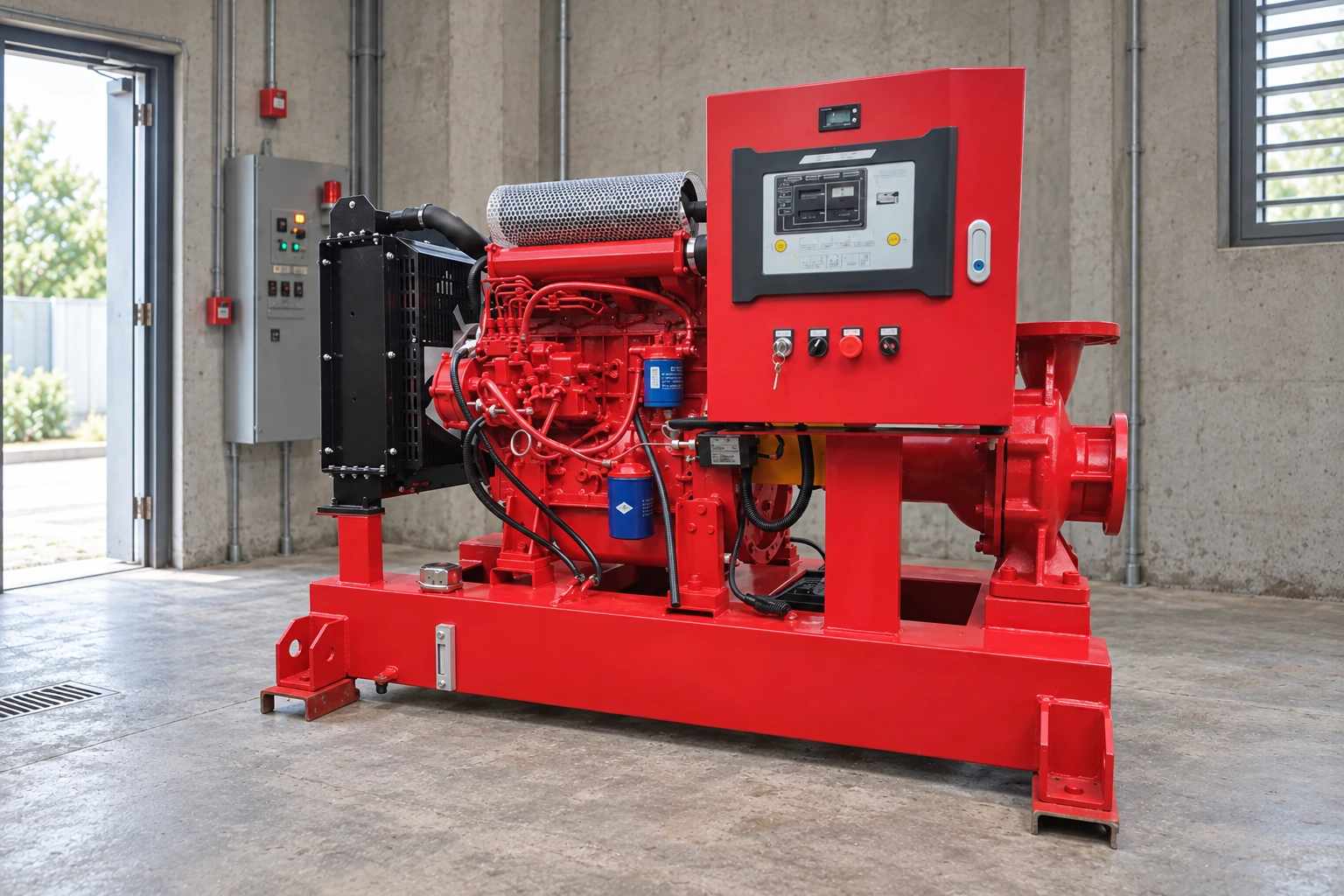
Trace the sensing arrangement on the current drawing. Check whether accessible valves and connections match the documented operating condition. A restricted, isolated or incorrectly connected sensing path can make a controller respond to a pressure that does not represent the intended system boundary.
A calibration check needs a suitable reference and a controlled procedure. Record the instrument ranges, units and measurement points. Apparent differences can result from elevation or connection location as well as instrument error. Avoid deciding which reading is correct merely because one appears on a newer digital display.
Sử dụng Hướng dẫn bộ điều khiển bơm bù áp for the broader sequence and documentation review. Preserve approved settings during diagnosis. Raising or lowering setpoints without resolving a measurement error can introduce a second problem and obscure the original cause.
Restore service with a documented normal cycle
After an approved repair, demonstrate the intended pressure-maintenance cycle and confirm that temporary test arrangements have been removed. Check the normal automatic condition, alarms and relevant valve positions under the site’s restoration procedure. A pump becoming quiet is not sufficient evidence that protection has been restored.
Keep a before-and-after record: pressure trend, running time, start count, fault finding, corrective work and witnessed result. Compare with the jockey pump pressure settings guide and the project’s actual approved schedule. No generic online example can approve the final values for every system.
The HSE pressure systems safety guide provides general context for managing stored pressure during service work. Apply the equipment-specific isolation procedure and fire-system impairment arrangements rather than treating a stopped motor as a fully isolated system.
Further learning: why pressure depends on the system
Practical Engineering’s “Do Pumps Create Pressure or Flow?” offers useful background for understanding the difference between a running pump and a system that can reach its target pressure. It does not demonstrate fire-pump controls, authorize setpoints or replace the troubleshooting and restoration procedures above.
Các câu hỏi thường gặp
Does continuous jockey pump operation always mean a leak?
No. Water loss is one possibility, but insufficient delivery, incorrect sensing, an active command or documented timing behavior can also explain it. Use pressure and command observations together before assigning a cause.
Is frequent cycling the same problem as continuous running?
They are different operating patterns. Cycling includes repeated stops and restarts; continuous operation has no normal stop. Record which pattern occurs because the pressure recovery and decay observations lead to different checks.
Should I increase the stop pressure?
Do not change an approved setting to mask the symptom. First verify the pressure readings, available pump performance and original control sequence. Setting changes require review of system limits and coordination.
Can I switch off the main fire pump during diagnosis?
Do not disable fire protection as an informal troubleshooting step. Any action that affects availability must follow the site’s approved impairment process and be directed by responsible qualified personnel.
What should the service team receive before attending?
Send the model and controller details, current approved settings, pressure and time observations, alarms, operating mode and recent work history. Include whether pressure rises, remains flat or reaches the stop condition while the motor continues.