
Size fire pump discharge piping for the required operating and test flows, acceptable friction and velocity, downstream pressure limits, and the approved valve and test arrangement. Begin at the pump discharge and trace every fitting, check valve, isolation valve, header, branch, riser, meter, and pressure-control device. The pipe must carry the required flow without consuming excessive pump head or creating damaging transients, while remaining accessible for inspection and testing. Keep the calculation and acceptance record with the final project documents so future tests use the same basis.
السلام والنشاط: مضخات الحريق ومحركاتها هي معدات للسلامة في الحياة. يجب أن تتوافق أعمال الأنظمة الهيدروليكية، والكهربائية، والديزل، والوقود، والبطاريات، والضغط، والمعدات الدوارة، والاختبار، وتعطيل الأنظمة مع التصميم الحالي المعتمد، وتتعليمات الشركة المصنعة، والمعايير المطبقة، والجهة المختصة ذات الصلاحية. يوضح هذا الدليل مسار القرار الهندسي؛ ولا يمنح الإذن بإجراء تعديلات ميدانية، أو تجاوزات، أو تشغيل بواسطة أشخاص غير مؤهلين.
Establish operating and test flows
List rated demand, maximum approved test flow, and any simultaneous branches. Use the governing case for each part of the discharge network. Treat this as a system condition rather than an isolated component choice. Identify the source of every input, the unit used, the operating condition it represents, and the person responsible for approval. If information is preliminary, mark the assumption and test how the decision changes at a conservative boundary. This prevents a neat calculation from hiding an uncertain water level, pressure, valve position, driver condition, or simultaneous demand.
For fire pump discharge pipe sizing, verify this section against the selected pump curve, the actual site arrangement, manufacturer instructions, and the current requirements accepted by the authority having jurisdiction. Check the installed condition as well as the drawing because pipe routes, elevations, supports, controls, and access often change during construction. Record the result in a form that can be repeated during commissioning and later inspection. Do not change a safety-critical setting or isolate fire protection without the approved impairment and restoration process.
Calculate velocity and friction
Use actual internal diameter and a recognized hydraulic method. Model fittings and valves rather than replacing a complex route with an unsupported allowance. The most useful evidence is measured or approved project data, not a copied rule of thumb. Identify the source of every input, the unit used, the operating condition it represents, and the person responsible for approval. If information is preliminary, mark the assumption and test how the decision changes at a conservative boundary. This prevents a neat calculation from hiding an uncertain water level, pressure, valve position, driver condition, or simultaneous demand.
For fire pump discharge pipe sizing, verify this section against the selected pump curve, the actual site arrangement, manufacturer instructions, and the current requirements accepted by the authority having jurisdiction. Check the installed condition as well as the drawing because pipe routes, elevations, supports, controls, and access often change during construction. Record the result in a form that can be repeated during commissioning and later inspection. Do not change a safety-critical setting or isolate fire protection without the approved impairment and restoration process.
Account for static elevation
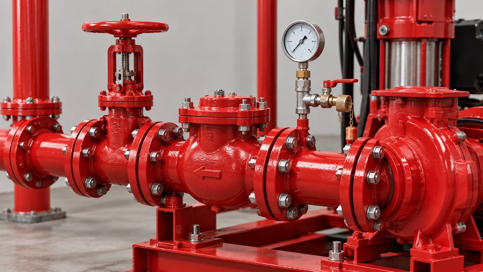
Vertical rise converts pump head into elevation head. High-rise systems may need zones or pressure-control arrangements to protect lower floors. Review this condition at normal, test, and credible abnormal states before procurement. Identify the source of every input, the unit used, the operating condition it represents, and the person responsible for approval. If information is preliminary, mark the assumption and test how the decision changes at a conservative boundary. This prevents a neat calculation from hiding an uncertain water level, pressure, valve position, driver condition, or simultaneous demand.
For fire pump discharge pipe sizing, verify this section against the selected pump curve, the actual site arrangement, manufacturer instructions, and the current requirements accepted by the authority having jurisdiction. Check the installed condition as well as the drawing because pipe routes, elevations, supports, controls, and access often change during construction. Record the result in a form that can be repeated during commissioning and later inspection. Do not change a safety-critical setting or isolate fire protection without the approved impairment and restoration process.
Place check and isolation valves
Follow the approved sequence and maintain access for operation, inspection, and replacement. Confirm that valve ratings exceed credible system pressure. The design team should turn this point into a traceable calculation or drawing note. Identify the source of every input, the unit used, the operating condition it represents, and the person responsible for approval. If information is preliminary, mark the assumption and test how the decision changes at a conservative boundary. This prevents a neat calculation from hiding an uncertain water level, pressure, valve position, driver condition, or simultaneous demand.
For fire pump discharge pipe sizing, verify this section against the selected pump curve, the actual site arrangement, manufacturer instructions, and the current requirements accepted by the authority having jurisdiction. Check the installed condition as well as the drawing because pipe routes, elevations, supports, controls, and access often change during construction. Record the result in a form that can be repeated during commissioning and later inspection. Do not change a safety-critical setting or isolate fire protection without the approved impairment and restoration process.
جدول قرارات عملي
| Discharge element | سؤال تصميمي | تحقق |
|---|---|---|
| Main pipe | Can it carry maximum required flow? | Hydraulic calculation |
| صمام عدم رجوع | Will it close reliably without severe surge? | Approved type and commissioning test |
| Isolation valve | Is position visible and access clear? | Field inspection |
| Test header or meter | Can the full test flow be measured safely? | Witnessed flow test |
| Relief route | Does it discharge to an approved safe location? | Drawing and field trace |
| يدعم | Are pump nozzles free of external load? | Alignment and support record |
Integrate test and relief routes
Size the test path to carry required flow safely to an approved destination. Relief or circulation lines must not create an unplanned bypass. Treat this as a system condition rather than an isolated component choice. Identify the source of every input, the unit used, the operating condition it represents, and the person responsible for approval. If information is preliminary, mark the assumption and test how the decision changes at a conservative boundary. This prevents a neat calculation from hiding an uncertain water level, pressure, valve position, driver condition, or simultaneous demand.
For fire pump discharge pipe sizing, verify this section against the selected pump curve, the actual site arrangement, manufacturer instructions, and the current requirements accepted by the authority having jurisdiction. Check the installed condition as well as the drawing because pipe routes, elevations, supports, controls, and access often change during construction. Record the result in a form that can be repeated during commissioning and later inspection. Do not change a safety-critical setting or isolate fire protection without the approved impairment and restoration process.
Review surge and water hammer
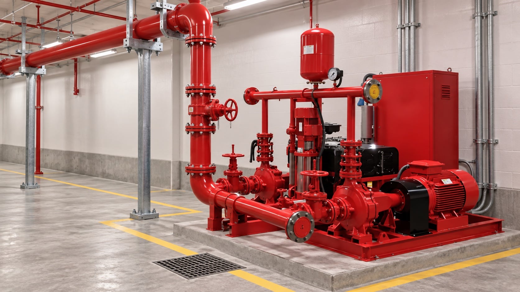
Rapid valve action, pump starting, and check-valve closure can create transient pressure. Coordinate a surge review where consequence or system geometry warrants it. The most useful evidence is measured or approved project data, not a copied rule of thumb. Identify the source of every input, the unit used, the operating condition it represents, and the person responsible for approval. If information is preliminary, mark the assumption and test how the decision changes at a conservative boundary. This prevents a neat calculation from hiding an uncertain water level, pressure, valve position, driver condition, or simultaneous demand.
For fire pump discharge pipe sizing, verify this section against the selected pump curve, the actual site arrangement, manufacturer instructions, and the current requirements accepted by the authority having jurisdiction. Check the installed condition as well as the drawing because pipe routes, elevations, supports, controls, and access often change during construction. Record the result in a form that can be repeated during commissioning and later inspection. Do not change a safety-critical setting or isolate fire protection without the approved impairment and restoration process.
Support and align the piping
Independent supports should control weight, vibration, and thermal movement without loading pump nozzles. Preserve coupling and valve maintenance clearance. Review this condition at normal, test, and credible abnormal states before procurement. Identify the source of every input, the unit used, the operating condition it represents, and the person responsible for approval. If information is preliminary, mark the assumption and test how the decision changes at a conservative boundary. This prevents a neat calculation from hiding an uncertain water level, pressure, valve position, driver condition, or simultaneous demand.
For fire pump discharge pipe sizing, verify this section against the selected pump curve, the actual site arrangement, manufacturer instructions, and the current requirements accepted by the authority having jurisdiction. Check the installed condition as well as the drawing because pipe routes, elevations, supports, controls, and access often change during construction. Record the result in a form that can be repeated during commissioning and later inspection. Do not change a safety-critical setting or isolate fire protection without the approved impairment and restoration process.
Verify the installed system
Check pipe size, route, supports, valve indication, flow direction, drainage, and test discharge. Record pressure and flow during acceptance. The design team should turn this point into a traceable calculation or drawing note. Identify the source of every input, the unit used, the operating condition it represents, and the person responsible for approval. If information is preliminary, mark the assumption and test how the decision changes at a conservative boundary. This prevents a neat calculation from hiding an uncertain water level, pressure, valve position, driver condition, or simultaneous demand.
For fire pump discharge pipe sizing, verify this section against the selected pump curve, the actual site arrangement, manufacturer instructions, and the current requirements accepted by the authority having jurisdiction. Check the installed condition as well as the drawing because pipe routes, elevations, supports, controls, and access often change during construction. Record the result in a form that can be repeated during commissioning and later inspection. Do not change a safety-critical setting or isolate fire protection without the approved impairment and restoration process.
كيف يرتبط هذا بمعدات BORRAPUMP
توفر شركة BORRAPUMP معدات ضخ هندسية لمشاريع المياه والحماية من الحريق. راجع ما يخص ذلك تكوين منتج BORRAPUMP كمنطلق، ثم قم بتقديم التدفق المطلوب، والرأس، ومصدر المياه، والمشغل، والطاقة، وأدوات التحكم، وظروف الموقع، والمتطلبات المطبقة، والكمية، والوجهة. يجب أن يستخدم الاختيار النهائي الأساس الهيدروليكي للمشروع والتقديم المعتمد؛ لا يدعي هذا الدليل أن ترتيباً واحداً في الكتالوج يناسب كل اختصاص أو مخاطرة.
أدلة BORRAPUMP ذات الصلة
- اختيار منظومة مضخات الحريق
- دليل اختبار قبول المعيار NFPA 20
- دليل الفحص والاختبار وفقاً للمواصفة NFPA 25
مراجع موثوقة
تحدد المصادر التالية حدود المعايير، وسياق السلامة من الحرائق، ومبادئ نظام المضخات المستخدمة في هذا الدليل. قم دائماً بتطبيق الإصدار والاعتماد المحلي المقبول للمشروع.
- صفحة تطوير معيار NFPA 20
- موارد أنظمة المضخات التابعة لوزارة الطاقة الأمريكية
- أبحاث المعهد الوطني للمعايير والتقنية (نيست) للحماية من الحريق
فيديو تعليمي

الخلفية التعليمية بواسطة الهندسة العملية: هل المضخات تولد ضغطاً أم تدفقاً؟. يدعم الفيديو مفهوم الهندسة الأساسي ولا يحل محل متطلبات الحماية من الحريق الخاصة بالمشروع.
الأسئلة الشائعة
Should discharge pipe match the pump flange?
Not necessarily. Size the system pipe from flow, loss, pressure, and installation requirements; use the correct transition at the pump.
Why calculate maximum test flow?
The test path and relevant piping must pass the required verification flow without unsafe pressure or discharge.
Can I use a pressure relief valve for normal control?
Routine pressure control requires an approved system design. A relief device should not compensate for an incorrectly selected pump.
What causes discharge water hammer?
Rapid changes in velocity, valve operation, and check-valve behavior can create transient pressure waves.
قائمة التحقق من التحقق النهائي
قبل الموافقة، قم بتأكيد الأساس الهيدروليكي، وحالة مصدر المياه، ومنحنى المضخة المختار، وبيانات المحرك ووحدة التحكم، وتصنيفات ضغط المكونات، وترتيب الصمامات، وطريقة الاختبار، وسُبل الوصول، والصرف، والإنذارات، وإجراءات إعادة التشغيل. قم بحل أي اختلافات بين المخططات والنظام المُركَّب. وأثناء التشغيل التجريبي، استخدم أدوات معايرة وسجّل ضغط السحب، وضغط الطرد، ومعدل التدفق، والسرعة، وحالة المحرك، والإنذارات، والملاحظات غير الطبيعية عند كل نقطة مطلوبة. احتفظ بالنتائج المقبولة مع سجلات غرفة المضخات لكي تُقارن عمليات الفحص اللاحقة النتائج المتشابهة ببعضها.