
Size fire pump discharge piping for the required operating and test flows, acceptable friction and velocity, downstream pressure limits, and the approved valve and test arrangement. Begin at the pump discharge and trace every fitting, check valve, isolation valve, header, branch, riser, meter, and pressure-control device. The pipe must carry the required flow without consuming excessive pump head or creating damaging transients, while remaining accessible for inspection and testing. Keep the calculation and acceptance record with the final project documents so future tests use the same basis.
Sicherheit und Geltungsbereich: Feuerlöschpumpen und deren Antriebe sind lebensrettende Einrichtungen. Arbeiten an Hydraulik, Elektrik, Diesel, Kraftstoff, Batterie, Druck, rotierenden Geräten, Prüfungen und Betriebsstörungen müssen dem aktuellen genehmigten Entwurf, den Herstelleranweisungen, den geltenden Normen und der zuständigen Behörde entsprechen. Dieser Leitfaden erläutert den ingenieurtechnischen Entscheidungsweg; er berechtigt nicht zu Änderungen vor Ort, Umgehungen oder zum Betrieb durch unqualifiziertes Personal.
Establish operating and test flows
List rated demand, maximum approved test flow, and any simultaneous branches. Use the governing case for each part of the discharge network. Treat this as a system condition rather than an isolated component choice. Identify the source of every input, the unit used, the operating condition it represents, and the person responsible for approval. If information is preliminary, mark the assumption and test how the decision changes at a conservative boundary. This prevents a neat calculation from hiding an uncertain water level, pressure, valve position, driver condition, or simultaneous demand.
For fire pump discharge pipe sizing, verify this section against the selected pump curve, the actual site arrangement, manufacturer instructions, and the current requirements accepted by the authority having jurisdiction. Check the installed condition as well as the drawing because pipe routes, elevations, supports, controls, and access often change during construction. Record the result in a form that can be repeated during commissioning and later inspection. Do not change a safety-critical setting or isolate fire protection without the approved impairment and restoration process.
Calculate velocity and friction
Use actual internal diameter and a recognized hydraulic method. Model fittings and valves rather than replacing a complex route with an unsupported allowance. The most useful evidence is measured or approved project data, not a copied rule of thumb. Identify the source of every input, the unit used, the operating condition it represents, and the person responsible for approval. If information is preliminary, mark the assumption and test how the decision changes at a conservative boundary. This prevents a neat calculation from hiding an uncertain water level, pressure, valve position, driver condition, or simultaneous demand.
For fire pump discharge pipe sizing, verify this section against the selected pump curve, the actual site arrangement, manufacturer instructions, and the current requirements accepted by the authority having jurisdiction. Check the installed condition as well as the drawing because pipe routes, elevations, supports, controls, and access often change during construction. Record the result in a form that can be repeated during commissioning and later inspection. Do not change a safety-critical setting or isolate fire protection without the approved impairment and restoration process.
Account for static elevation
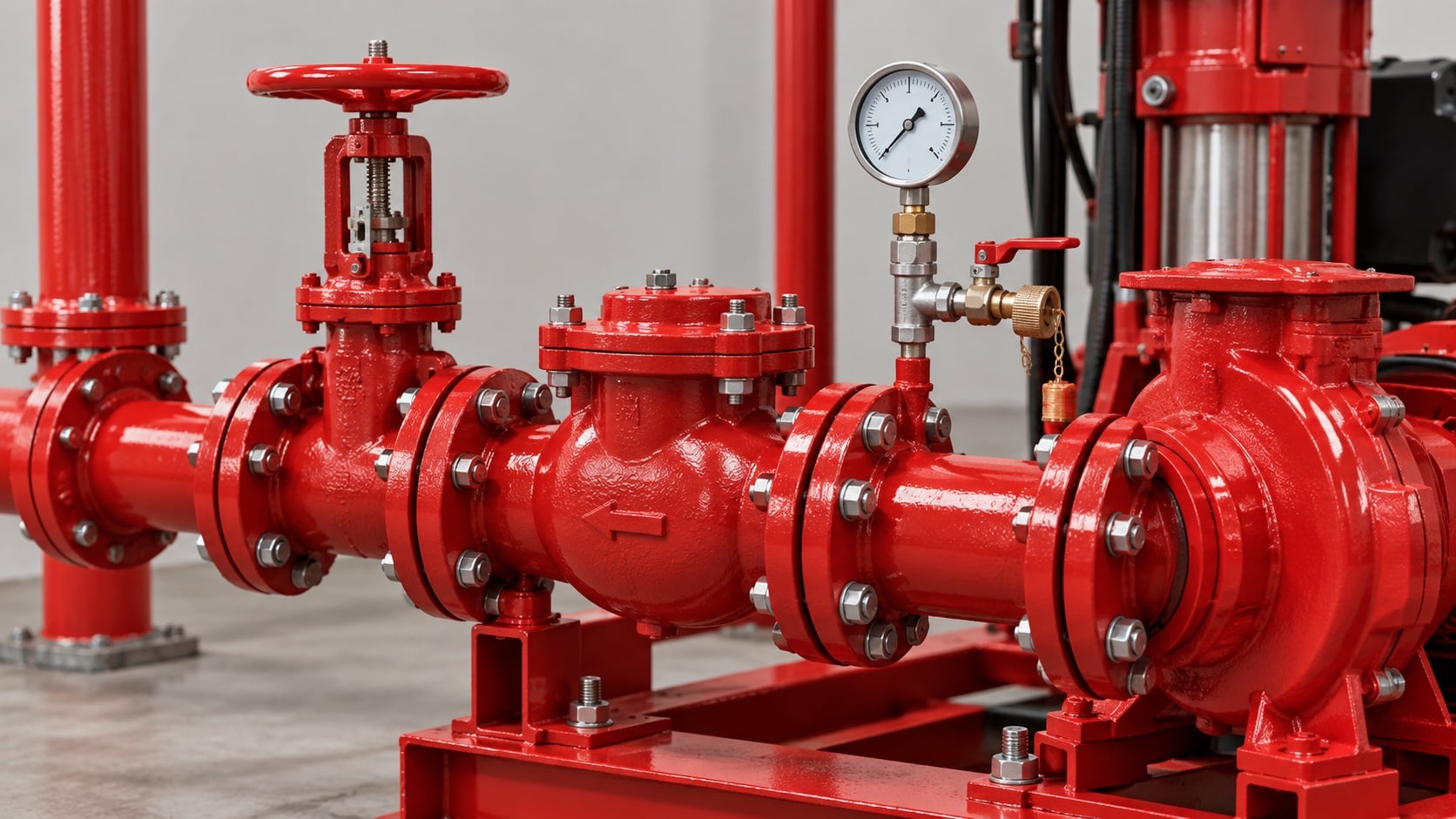
Vertical rise converts pump head into elevation head. High-rise systems may need zones or pressure-control arrangements to protect lower floors. Review this condition at normal, test, and credible abnormal states before procurement. Identify the source of every input, the unit used, the operating condition it represents, and the person responsible for approval. If information is preliminary, mark the assumption and test how the decision changes at a conservative boundary. This prevents a neat calculation from hiding an uncertain water level, pressure, valve position, driver condition, or simultaneous demand.
For fire pump discharge pipe sizing, verify this section against the selected pump curve, the actual site arrangement, manufacturer instructions, and the current requirements accepted by the authority having jurisdiction. Check the installed condition as well as the drawing because pipe routes, elevations, supports, controls, and access often change during construction. Record the result in a form that can be repeated during commissioning and later inspection. Do not change a safety-critical setting or isolate fire protection without the approved impairment and restoration process.
Place check and isolation valves
Follow the approved sequence and maintain access for operation, inspection, and replacement. Confirm that valve ratings exceed credible system pressure. The design team should turn this point into a traceable calculation or drawing note. Identify the source of every input, the unit used, the operating condition it represents, and the person responsible for approval. If information is preliminary, mark the assumption and test how the decision changes at a conservative boundary. This prevents a neat calculation from hiding an uncertain water level, pressure, valve position, driver condition, or simultaneous demand.
For fire pump discharge pipe sizing, verify this section against the selected pump curve, the actual site arrangement, manufacturer instructions, and the current requirements accepted by the authority having jurisdiction. Check the installed condition as well as the drawing because pipe routes, elevations, supports, controls, and access often change during construction. Record the result in a form that can be repeated during commissioning and later inspection. Do not change a safety-critical setting or isolate fire protection without the approved impairment and restoration process.
Praktische Entscheidungstabelle
| Discharge element | Designfrage | Verifizierung |
|---|---|---|
| Main pipe | Can it carry maximum required flow? | Hydraulic calculation |
| Rückschlagventil | Will it close reliably without severe surge? | Approved type and commissioning test |
| Isolation valve | Is position visible and access clear? | Field inspection |
| Test header or meter | Can the full test flow be measured safely? | Witnessed flow test |
| Relief route | Does it discharge to an approved safe location? | Drawing and field trace |
| Unterstützt | Are pump nozzles free of external load? | Alignment and support record |
Integrate test and relief routes
Size the test path to carry required flow safely to an approved destination. Relief or circulation lines must not create an unplanned bypass. Treat this as a system condition rather than an isolated component choice. Identify the source of every input, the unit used, the operating condition it represents, and the person responsible for approval. If information is preliminary, mark the assumption and test how the decision changes at a conservative boundary. This prevents a neat calculation from hiding an uncertain water level, pressure, valve position, driver condition, or simultaneous demand.
For fire pump discharge pipe sizing, verify this section against the selected pump curve, the actual site arrangement, manufacturer instructions, and the current requirements accepted by the authority having jurisdiction. Check the installed condition as well as the drawing because pipe routes, elevations, supports, controls, and access often change during construction. Record the result in a form that can be repeated during commissioning and later inspection. Do not change a safety-critical setting or isolate fire protection without the approved impairment and restoration process.
Review surge and water hammer
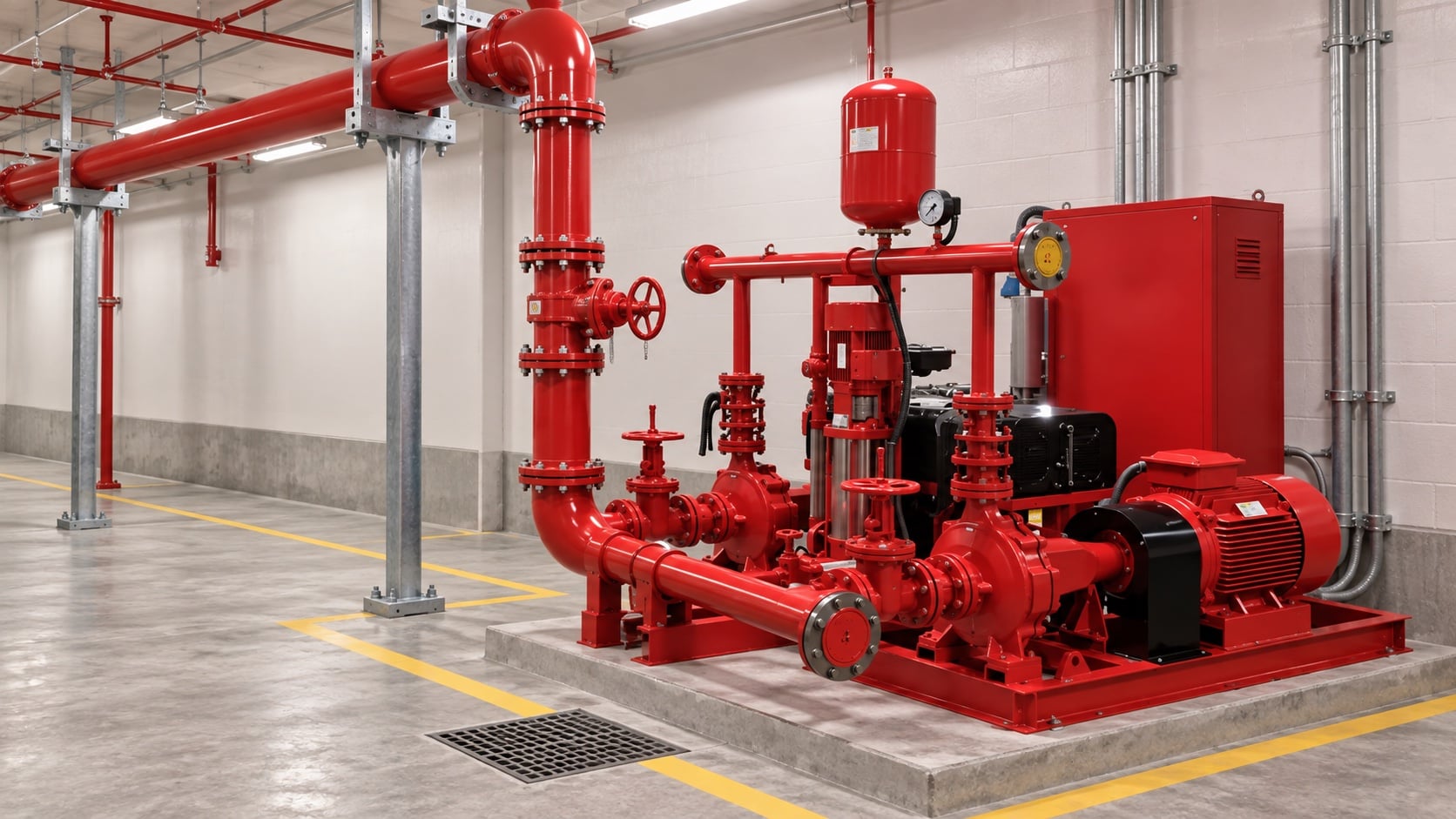
Rapid valve action, pump starting, and check-valve closure can create transient pressure. Coordinate a surge review where consequence or system geometry warrants it. The most useful evidence is measured or approved project data, not a copied rule of thumb. Identify the source of every input, the unit used, the operating condition it represents, and the person responsible for approval. If information is preliminary, mark the assumption and test how the decision changes at a conservative boundary. This prevents a neat calculation from hiding an uncertain water level, pressure, valve position, driver condition, or simultaneous demand.
For fire pump discharge pipe sizing, verify this section against the selected pump curve, the actual site arrangement, manufacturer instructions, and the current requirements accepted by the authority having jurisdiction. Check the installed condition as well as the drawing because pipe routes, elevations, supports, controls, and access often change during construction. Record the result in a form that can be repeated during commissioning and later inspection. Do not change a safety-critical setting or isolate fire protection without the approved impairment and restoration process.
Support and align the piping
Independent supports should control weight, vibration, and thermal movement without loading pump nozzles. Preserve coupling and valve maintenance clearance. Review this condition at normal, test, and credible abnormal states before procurement. Identify the source of every input, the unit used, the operating condition it represents, and the person responsible for approval. If information is preliminary, mark the assumption and test how the decision changes at a conservative boundary. This prevents a neat calculation from hiding an uncertain water level, pressure, valve position, driver condition, or simultaneous demand.
For fire pump discharge pipe sizing, verify this section against the selected pump curve, the actual site arrangement, manufacturer instructions, and the current requirements accepted by the authority having jurisdiction. Check the installed condition as well as the drawing because pipe routes, elevations, supports, controls, and access often change during construction. Record the result in a form that can be repeated during commissioning and later inspection. Do not change a safety-critical setting or isolate fire protection without the approved impairment and restoration process.
Verify the installed system
Check pipe size, route, supports, valve indication, flow direction, drainage, and test discharge. Record pressure and flow during acceptance. The design team should turn this point into a traceable calculation or drawing note. Identify the source of every input, the unit used, the operating condition it represents, and the person responsible for approval. If information is preliminary, mark the assumption and test how the decision changes at a conservative boundary. This prevents a neat calculation from hiding an uncertain water level, pressure, valve position, driver condition, or simultaneous demand.
For fire pump discharge pipe sizing, verify this section against the selected pump curve, the actual site arrangement, manufacturer instructions, and the current requirements accepted by the authority having jurisdiction. Check the installed condition as well as the drawing because pipe routes, elevations, supports, controls, and access often change during construction. Record the result in a form that can be repeated during commissioning and later inspection. Do not change a safety-critical setting or isolate fire protection without the approved impairment and restoration process.
Wie dies sich auf BORRAPUMP-Ausrüstung bezieht
BORRAPUMP liefert technische Pumpenausrüstung für Wasser- und Brandschutzprojekte. Überprüfen Sie die relevanten BORRAPUMP-Produktkonfiguration als Ausgangspunkt, reichen Sie dann den erforderlichen Volumenstrom, die Förderhöhe, die Wasserquelle, den Antrieb, die Leistung, die Steuerungen, die Baustellenbedingungen, die geltenden Anforderungen, die Stückzahl und den Bestimmungsort ein. Die endgültige Auswahl muss auf der hydraulischen Projektbasis und der genehmigten Einreichung basieren; dieser Leitfaden erhebt keinen Anspruch darauf, dass eine Kataloganordnung für jede Jurisdiktion oder jedes Risiko passt.
Ähnliche BORRAPUMP-Anleitungen
- Auswahl der Feuerlöschpumpen-Einheit
- NFPA 20 Abnahmeprüfungs-Leitfaden
- Leitfaden für Inspektion und Prüfung nach NFPA 25
Maßgebliche Referenzen
Die folgenden Quellen legen den Normenbereich, den Brandschutzkontext und die Pumpensystemprinzipien fest, die in diesem Leitfaden verwendet werden. Wenden Sie stets die für das Projekt akzeptierte Ausgabe und lokale Einführung an.
- NFPA 20 Normenentwicklungsseite
- Ressourcen für Pumpensysteme des US-Energieministeriums
- NIST-Forschung zum Brandschutz
Lernvideo

Bildungshintergrund von Practical Engineering: Erzeugen Pumpen Druck oder Fluss?. Das Video unterstützt das zugrundeliegende ingenieurtechnische Konzept und ersetzt nicht die projektspezifischen Brandschutzanforderungen.
Häufig gestellte Fragen
Should discharge pipe match the pump flange?
Not necessarily. Size the system pipe from flow, loss, pressure, and installation requirements; use the correct transition at the pump.
Why calculate maximum test flow?
The test path and relevant piping must pass the required verification flow without unsafe pressure or discharge.
Can I use a pressure relief valve for normal control?
Routine pressure control requires an approved system design. A relief device should not compensate for an incorrectly selected pump.
What causes discharge water hammer?
Rapid changes in velocity, valve operation, and check-valve behavior can create transient pressure waves.
Abschließende Prüfliste
Vor der Freigabe sind die hydraulischen Grundlagen, die Wasserquellenbedingungen, die ausgewählte Pumpenkennlinie, die Daten von Antrieb und Steuerung, die Nenndrücke der Komponenten, die Ventilanordnung, das Prüfverfahren, die Zugänglichkeit, die Entwässerung, die Alarme und das Wiederherstellungsverfahren zu bestätigen. Differenzen zwischen den Zeichnungen und dem installierten System sind zu berechnen. Während der Inbetriebnahme sind kalibrierte Instrumente zu verwenden und Saugdruck, Förderdruck, Durchfluss, Drehzahl, Antriebszustand, Alarme und abweichende Beobachtungen an jedem geforderten Punkt aufzuzeichnen. Die akzeptierten Ergebnisse sind bei den Pumpenraumprotokollen aufzubewahren, damit spätere Inspektionen vergleichbare Werte liefern.