
A pump system curve shows the head a piping system requires at different flow rates. For a simple water-transfer installation it combines static head with flow-dependent friction and equipment losses. Plotting that requirement against the selected pump curve identifies an expected operating point; neither curve alone tells you the installed flow. Build the curve from the actual route, source and destination pressures, water levels, internal pipe diameters, fittings and equipment. Then test more than one operating condition. A single attractive duty point can hide inadequate flow at low source level or excessive flow when a clean filter and open valves reduce resistance.
This guide concerns a defined incompressible liquid circuit. Its numerical example illustrates the method rather than rating a BORRAPUMP model. Branching networks, variable demand, two-phase flow and controls may need a network calculation instead of one fixed resistance line.
Define the two calculation boundaries
Draw a line from the source boundary to the destination boundary before adding losses. An open tank water surface is different from a pump inlet flange. If the source is a pressurized header, record its available pressure and the location where that pressure applies. If the destination is another open tank, use its water level; if the destination requires residual pressure, include that requirement explicitly.
Record whether each pressure is gauge or absolute. Use one consistent datum for elevations and one consistent liquid density for pressure-to-head conversion. Including the same suction pipe loss both inside a measured inlet pressure and again as a separate loss will overstate the required pump head. Omitting a downstream control valve produces the opposite error. A simple annotated sketch often prevents more mistakes than a more elaborate spreadsheet.
ال centrifugal pump selection guide explains the equipment decision after this system boundary has been established. The system calculation should describe the installation without assuming that a particular pump will fit it.
Separate static head from resistance
Static head is the elevation and pressure requirement that remains when the defined steady flow tends toward zero. For transfer between open tanks, it includes the difference between the two free surfaces. A destination pressure greater than the source pressure adds another term, converted into metres or feet of the liquid being pumped. Static head may change as tanks fill or empty.
Pipe friction, fitting losses and many equipment losses vary with flow. For turbulent flow in a fixed route, an approximate quadratic relationship is often useful over a limited operating range. It is an approximation, not a universal law: the friction factor can change with Reynolds number and roughness, and some equipment has its own measured loss characteristic. Use the supplier’s curve for a filter, heat exchanger or other component when available.
Build the curve from consistent inputs
For a simple route, write H_system = H_static + H_loss. If a justified quadratic approximation is used, write H_loss = KQ² and state the flow units associated with K. A coefficient calculated with cubic metres per hour cannot be reused unchanged with litres per second. Keep the original units beside every coefficient.
Calculate straight-pipe loss using the true internal diameter rather than the nominal label. Include the actual pipe length, fittings, valves, strainers and devices within the boundary. Document roughness assumptions and the expected water temperature. The suction pipe sizing article addresses a related constraint: reducing a suction loss can improve inlet conditions, but the inlet still needs its own pressure and priming checks.
Create several flow rows across the plausible operating range. Do not extrapolate a single measured point indefinitely. Where static pressure is uncertain, use separate credible cases so that the calculation shows the effect rather than concealing uncertainty in an arbitrary safety allowance.
Work through an illustrative water-transfer example
Suppose two open tank surfaces differ by 12 metres at the condition being analysed. An independently calculated route loss is 8 metres at 40 cubic metres per hour. For this demonstration only, assume that the same route can be represented by quadratic losses. The coefficient is 8 divided by 40 squared, or 0.005 when flow is expressed in cubic metres per hour and head in metres.
At 20 cubic metres per hour the estimated loss is 2 metres, giving 14 metres total head. At 40 it is 8 metres, giving 20 metres total. At 60 it is 18 metres, giving 30 metres total. These are points on a hypothetical system curve; they are not three operating ratings of a pump. The pump must still be selected and checked against its documented curve.
| Flow, m³/h | Static head, m | Estimated route loss, m | System head, m |
|---|---|---|---|
| 0 | 12 | 0 | 12 |
| 20 | 12 | 2 | 14 |
| 40 | 12 | 8 | 20 |
| 60 | 12 | 18 | 30 |
The table follows the stated illustrative equation. Its quadratic assumption must be replaced if the actual equipment or fluid does not follow that relationship. No energy use or pipe size should be purchased from this example.
Find the intersection and check the limits
Overlay the pump head curve for the offered speed, impeller and liquid. Its intersection with the system curve gives an expected steady operating point for that configuration. Use the pump curve reading checklist to confirm that efficiency, shaft power and NPSH data refer to the same configuration and flow.
An intersection is necessary but does not by itself establish acceptable operation. Check the manufacturer’s permitted operating range, motor loading, inlet conditions, casing pressure limits and downstream pressure requirements. A pump can intersect the system curve while operating too far from its intended region. An unstable or unusually shaped characteristic may also require specialist assessment instead of a simple graphical selection.
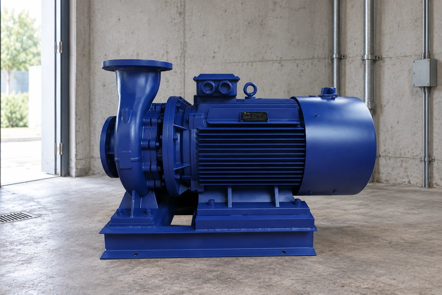
أنا مضخة المياه المركزية من نوع IS can be a relevant product family to discuss for a clean-water transfer duty. Its photograph does not establish the curve: request the exact model, speed, impeller and certified operating information for the proposed project.
Draw more than the normal condition
A low source level raises the required static lift for an open-tank transfer and may also reduce available suction head. A higher destination level raises the delivery requirement. Dirty filters and partly closed valves raise resistance. A different branch configuration may change the entire network rather than merely shifting one constant.
At the other extreme, a full source tank, low destination level and newly cleaned equipment can reduce resistance. Check this case for excessive flow and motor loading. Selecting only against the most restrictive case can overlook an unacceptable operating point when the system is easier to pump through. Keep both cases in the selection record and identify which controls prevent operation beyond approved limits.
Distinguish control action from system physics
A throttling valve changes resistance, while a speed change alters the pump curve. A pressure controller moves the operating condition as demand changes; it does not turn every condition into the same fixed system curve. In a distribution system, multiple outlet demands and pressure zones may require a family of curves or a network model.
Avoid treating a constant discharge pressure as constant pump differential head when inlet pressure varies. Likewise, adding a second parallel pump does not guarantee twice the flow because the new combined pump characteristic intersects the system at a different point. Record the control sequence, operating pump count and valve positions alongside each modelled case.
Confirm the calculation during commissioning
Measure flow and the relevant pressures simultaneously after stable operation is established. Record tank levels, pump speed, running pump count and the condition of filters and valves. Convert flange pressure readings into pump head consistently, including elevation and velocity effects when material. A pressure reading by itself is not a complete flow test.
Compare the observed point with both the pump curve and the predicted system requirement. Investigate instrument range, trapped air in sensing connections, incorrect valve position and as-built pipe differences before changing the pump. Several controlled operating points can help reveal whether the assumed static term or loss coefficient is wrong. Tests must stay inside the equipment’s operating limits and the site’s safe operating procedure.
Keep a useful selection record
Save the boundary sketch, assumptions, component loss data, calculated cases and marked pump curves together. Identify input values that came from measurements and values that were estimated. Record who should confirm uncertain incoming pressure, tank levels or future demand. Recalculate when the route or control arrangement changes.
ال دليل مصادر ضخ الطاقة في وزارة الطاقة الأمريكية describes the importance of matching pumps to system requirements. Its pumping systems resources provide further material on system assessment. These sources support the method; they do not approve a model for an unmeasured installation.
Further learning: NPTEL explains centrifugal pump characteristics. Use this educational background with the model-specific data and method discussed above; the lecture does not certify a BORRAPUMP model.
الأسئلة الشائعة
Does the system curve come from the pump manufacturer?
The system requirement comes from the installation. The manufacturer provides the proposed pump characteristic. The two must be compared using consistent units, liquid conditions and operating assumptions.
Must every system curve start at zero head?
No. A transfer system with a static elevation or pressure difference has a nonzero static term. A fully closed circulation loop may have no net elevation lift around the complete loop, while still requiring head to overcome losses.
Can I use the pump flange diameter as the pipe diameter?
No. Determine the actual internal diameter of each pipe section. The pump connection is only one component and does not establish route friction or the best system pipe size.
Why did flow increase after cleaning a strainer?
Cleaning can reduce resistance, moving the intersection to a higher flow on the same pump curve. Confirm the measured condition and keep the new operating point within the manufacturer’s limits.
Is one measured operating point enough?
One point can verify a particular condition but cannot establish every possible route or level case. Use additional safe measurements and documented component data when the operating envelope matters.