
Fire Pump System Diagram: Direct Answer A fire pump system diagram must separate the fire-flow path from the pressure-maintenance path. Read the drawing from water source to discharge header, then identify the main fire pump, jockey pump, controllers, valves…
Fire Pump System Diagram: Direct Answer
A fire pump system diagram must separate the fire-flow path from the pressure-maintenance path. Read the drawing from water source to discharge header, then identify the main fire pump, jockey pump, controllers, valves, test route, and the boundary between package supply and site installation.

1. Start With the Water Supply and Suction Path
The drawing should identify the water source, suction pipe, isolation points, and the connection to the main fire pump. Source condition is a project engineering input; a supplier drawing does not prove that water supply is sufficient for the required fire-flow duty.
| Diagram area | Review question |
|---|---|
| Water source | Is the intended source and supply boundary defined? |
| Suction connection | Are connection size and isolation shown? |
| Main pump inlet | Does it match the package arrangement? |
2. Identify the Main Fire-Flow Path
The main fire pump handles the required fire-flow duty. Its discharge path normally includes protective and isolation components before the system header. The exact arrangement belongs to the project design, not to a generic article.
3. Read the Jockey Pump Branch Separately
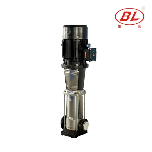
A jockey pump maintains pressure against small losses; it is not the main fire-flow pump. Its branch should show independent connections and a pressure-maintenance role so readers do not confuse its duty with the main pump rating.
| Pump role | Purpose | Key review point |
|---|---|---|
| Main fire pump | Deliver fire-flow duty | Required flow and pressure |
| Jockey pump | Maintain system pressure | Separate maintenance duty |
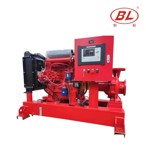
| Standby diesel pump if specified | Support package design | Driver, fuel, and controller scope |
4. Check Valves, Controllers, and Sensing Lines
Check valves prevent unwanted reverse flow. Controllers receive pressure inputs and manage the defined start sequence. A sensing line must be shown clearly enough for the engineer and installer to confirm what pressure reference the controller sees.
5. Locate Test and Drain Paths
A complete project drawing identifies the test route, drain points, and relevant isolation. Do not infer missing acceptance or inspection details from a marketing layout. Project documents and the authority review process govern the final installation.
6. Review an EDJ Package as a Supply Boundary
An EDJ package can combine electric fire pump, diesel standby pump, and jockey pump equipment. Review the supplied drawing against the project fire-protection design and list which controllers, valves, drivers, documents, and site connections are included.
| RFQ input | Why it is needed |
|---|---|
| Required flow and pressure | Defines main pump duty |
| Water source and suction condition | Defines package interface |
| Driver preference | Defines electric/diesel scope |
| Controller and documents | Defines commercial scope |
7. Fit Boundary
This guide explains diagram-reading and procurement checks. It does not certify a system, claim UL, FM, NFPA approval, or replace a project engineer, insurer, or authority having jurisdiction.
FAQ
What is the first line to trace on a fire pump system diagram?
Start at the water source and suction path, then follow the main pump discharge to the system header.
Is a jockey pump the same as a fire pump?
No. It maintains pressure for small losses while the main fire pump serves fire-flow duty.
Can a supplier diagram replace an engineer drawing?
No. Supplier drawings define package scope; project drawings define the accepted system arrangement.
What should a fire pump RFQ include?
Required flow, pressure, water source, driver preference, controller requirements, connection data, documents, and destination.
Does this article claim UL or FM approval?
No. Approval status must be verified for the exact product and project.
When is an EDJ package relevant?
When a project needs integrated electric, diesel, and jockey pump equipment subject to engineering review.
References
For a package discussion, send verified project data through contact Borra.