
A booster pump piping diagram should separate the water path from the control path and clearly identify supplier versus site piping. This guide helps MEP reviewers, installers, and project buyers identify the scope questions that must be resolved before site work. For the cluster overview, see the Booster Pumps guide.
Contents
- Part 1. What Should the Diagram Identify?
- Part 2. How Do You Trace the Main Path?
- Part 3. Which Protection and Control Elements Matter?
- Part 4. How Do Packaged and Field Connections Differ?
- Part 5. Which Review Errors Delay Commissioning?
- Part 6. Which BORRAPUMP Routes Fit the Layout?
- Part 7. What Are the Fit Boundaries?
- FAQ
Part 1. What Should the Diagram Identify?
A booster pump piping diagram is useful only when it identifies the path that affects pressure and the interfaces that affect installation. A pump model name does not show whether the site provides valves, panels, sensors, supports, or test points.
| Diagram layer | Reader should identify | Why the item changes the project |
|---|---|---|
| Water Source | Origin and condition at booster inlet | Establishes available pressure or electrical supply |
| Suction Line | Connection route and isolation | Defines service and installation boundary |
| Pump | Equipment and rating | Connects the drawing to the selected duty |
| Discharge Check Valve | Protection or control interface | Avoids reverse flow or false signals |
| Building Header | Downstream handoff | Defines system responsibility |
Hydraulic Institute guidance frames pump selection as a system interaction. The drawing should therefore be read with the required flow, pressure, and inlet condition — not separately from them.
Part 2. How Do You Trace the Main Path?
Start at the upstream interface, then follow each line to the booster package and finally to the distribution header. Mark every point where another contractor must connect, isolate, support, or test the system. This is more reliable than reading the drawing from the controller outward.
| Review sequence | What to confirm | Typical omission |
|---|---|---|
| Source or incoming feed | Capacity is stated at operating condition | Static value substituted for dynamic condition |
| Isolation point | Equipment can be serviced safely | Valve inaccessible after installation |
| Booster package | Pump count and controller match quote | Marketing drawing mistaken for final GA |
| Downstream protection | Check/overload role and direction are clear | Protection omitted from supply scope |
| Building connection | Header or terminal destination known | Field tie-in left undefined |
For selection context, use residential booster pump selection when the project must prove inlet conditions before choosing a booster.
Part 3. Which Protection and Control Elements Matter?
The diagram should distinguish hydraulic elements from control elements. In a constant-speed package, pressure switch and tank relationships are often central. In a VFD package, the pressure transducer, controller, and motor protection become the critical interfaces.
| Element | Piping review question | Failure if misunderstood |
|---|---|---|
| Isolation valve or disconnect | Is it on the correct service side? | Unsafe maintenance or downtime |
| Check valve or overload | Is its direction/rating identified? | Reverse flow or motor trips |
| Tank branch or pressure sensor | Does it see the controlled condition? | Cycling or unstable pressure |
| Controller terminal or panel | Is it factory-installed or field-wired? | Commissioning scope dispute |
| Gauge, alarm, or test point | Can the system be diagnosed? | No usable acceptance evidence |
Armstrong domestic booster guidance is useful for understanding that booster controls are part of the package decision rather than an afterthought.
Part 4. How Do Packaged and Field Connections Differ?
| Layout | Usually factory scope | Usually site scope |
|---|---|---|
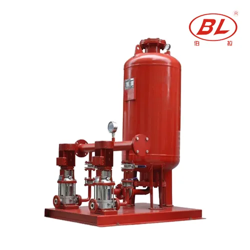
| Packaged booster skid | Pumps, manifold, panel, basic instruments | Incoming connection, anchors, power feed, outgoing header |
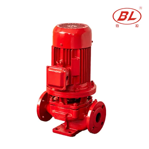
| Inline mechanical-room pump | Pump and motor assembly | Most valves, supports, control panel, spool pieces |
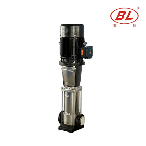
| Multistage booster | Pump assembly and motor | Service clearance, piping support, system controls |
Ask the supplier to label every terminal, flange, or pipe connection as factory furnished or by others. That simple scope note often prevents a low-price quote from becoming a delayed site installation.
Part 5. Which Review Errors Delay Commissioning?
| Review error | Why it delays the project | Better action |
|---|---|---|
| Treating a concept diagram as construction detail | Missing dimensions and elevations | Request project-specific GA and connection data |
| Ignoring source condition | Duty point becomes invalid | Record inlet pressure at peak demand |
| Assuming accessories are included | Unplanned valves or panel work | Compare line-item supply scope |
| Mixing fire-pump and booster requirements | Different approval and control rules | Route fire duty separately |
| No access allowance | Pump or panel cannot be serviced | Check removal and door-clearance route |
Pumps & Systems technical articles consistently separate the pump itself from the installation conditions that determine dependable operation.
Part 6. Which BORRAPUMP Routes Fit the Layout?
| Project signal | BORRAPUMP route | Boundary |
|---|---|---|
| Packaged building pressure boosting | Booster Regulator Water Supply Equipment | Confirm flow, head, and controls |
| Inline mechanical-room boost | ISG Vertical Inline Boost Water Pump | Confirm header arrangement |
| Higher-head multistage duty | CDL(F) Vertical Multistage Jockey Pump | Confirm curve and service space |
RFQ checklist
| Data item | Why the supplier needs it |
|---|---|
| Marked piping drawing | Confirms interface and scope |
| Flow and required outlet pressure | Defines duty point |
| Inlet pressure at peak flow | Confirms required boost |
| Control preference and power supply | Selects panel and motor approach |
| Installation environment and destination | Sets enclosure and export scope |
Send the completed information through contact Borra.
Product recommendation
The product routes above are starting points only. Do not route well lifting, sewage handling, or listed fire-pump duties through a general building booster layout.
Part 7. What Are the Fit Boundaries?
A concept piping diagram does not replace project hydraulic calculations, code review, or a dimensioned installation drawing. The final layout must be reviewed against the supplier documents, project engineer's drawings, and local installation requirements.
FAQ
What is the first thing to check on a booster pump piping diagram?
Start with the upstream interface and verify that the available supply condition is stated for the operating duty.
Is a concept diagram enough for installation?
No. A concept diagram explains functional order but project installation requires dimensions, connection data, and approved site documents.
Who supplies valves and accessories?
It depends on the quotation. The drawing and commercial scope should clearly separate factory-furnished items from field-supplied items.
Does every booster use a pressure tank?
No. Constant-speed systems more often use a tank; VFD layouts may use a smaller tank or a different control arrangement.
Why does inlet condition appear on the drawing?
It determines whether the booster can achieve the required added head without unstable suction conditions.
Can this diagram be used for a fire pump package?
No. Fire pump packages have separate approval, controller, and jockey-pump requirements.
What should be included in an RFQ?
Send the marked diagram, duty point, inlet condition, control preference, power supply, required documents, and destination.
Which BORRAPUMP product should I review first?
Start with Booster Regulator Water Supply Equipment for a packaged building booster, then confirm whether inline or multistage routes match the verified duty.