
Pump wear-ring retention inspection establishes whether a replaceable ring remains correctly located and secured in its supporting component. It examines the seat, locating features and specified locking arrangement, rather than simply measuring the running clearance. A satisfactory gap does not prove that a loose or incorrectly retained ring can return to service. Identify the actual construction from the pump drawing, document evidence of movement and obtain an approved repair or replacement decision. This guide provides an inspection workflow for pumps that use replaceable wear rings; it does not claim that every pump has them or specify a universal interference fit.
Separate retention from the running clearance
The running clearance concerns the space between opposing surfaces during operation. Retention concerns how each replaceable ring stays in its intended location. These are related but distinct checks. A ring might have an acceptable measured bore while its mounting seat or locking feature is damaged. Conversely, a securely mounted ring may still have unacceptable running wear.
Begin by identifying stationary and rotating components on the assembly drawing. Establish whether the feature is a replaceable ring, an integral machined surface or another form of restriction. Record part numbers and the applicable repair dimensions before interpreting an apparent joint. The wear-ring clearance guide addresses the hydraulic gap. Keep the retention report separate enough that a signed clearance measurement cannot be mistaken for acceptance of the mounting fit and locking arrangement.
Obtain the construction and repair documents
Collect the equipment identity, sectional drawing, parts list and previous repair records. Identify the approved retention method and any applicable locking components. Do not assume that a screw, pin, shoulder or visible mark has the same function across different pump designs. The controlled drawing must establish what should be present and how it is inspected.
The EPRI centrifugal-pump maintenance resource includes examination of wear-ring locking features within a wider pump inspection. Its relevance here is the need to inspect security as well as wear. It is not a dimensional acceptance sheet for a BORRAPUMP model. Where documents are incomplete, photograph the assembly and request a written disposition from the responsible supplier or engineer. Avoid dismantling an uncertain locking arrangement destructively before recording how the existing components are located.
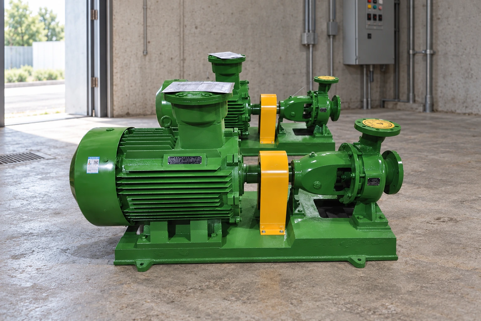
Record signs of movement before cleaning
After isolation and safe dismantling, photograph the ring and its supporting surface as found. Look for displaced witness marks, fretting debris, uneven contact, damaged locking features and evidence that a ring has rotated or shifted. Record the location and orientation of each observation. Distinguish actual evidence from an interpretation: a polished band may suggest contact, but it does not independently explain why movement occurred.
Keep removed locking components with the associated ring and housing or impeller identification. Avoid mixing similar rings from opposite ends or separate stages. If a ring is already loose, preserve that finding instead of reseating it for a tidier photograph. Handling can erase evidence of movement or create new marks. An inspection report should state whether an observation was made before removal, after cleaning or during a dimensional check.
Clean and examine the locking features
Use a cleaning method compatible with the ring and supporting material. Expose the accessible contact areas without rounding edges or removing evidence through uncontrolled polishing. Examine visible locking components for cracks, deformation, damaged engagement or missing material. Record any previously repaired area and identify it against the repair documentation.
Do not tighten an unknown locking screw, peen a surface or apply an adhesive merely to make the ring feel secure. Such changes can alter the assembly without establishing an acceptable repair. If a component must be removed for proper examination, follow the approved sequence and use suitable tooling. Safety planning remains essential: the HSE maintenance guidance provides general UK context for controlling maintenance hazards. It does not establish the safe removal force, heating method or temperature for this particular ring and support.
| Inspection area | Evidence to collect | Decision that remains equipment-specific |
|---|---|---|
| Ring identification | Part number, location and material record | Correct replacement specification |
| Locating shoulder | Contact marks, damage and measured position | Acceptable seating condition |
| Mounting seat | Dimensions, surface condition and movement evidence | Required fit and repair limit |
| Locking component | Identity, condition and engagement details | Reuse or mandatory replacement |
| Installed position | Drawing-based reference measurements | Accepted axial and radial location |
The table describes documentation tasks, not numerical tolerances or a replacement design.
Assess the supporting seat as a mating component
A retention failure may involve the casing or impeller seat rather than only the ring. Examine accessible supporting surfaces for scoring, corrosion, displaced metal and evidence of relative movement. Use a defined measurement plan to record relevant dimensions at identified positions. Avoid treating a single convenient reading as a complete assessment of roundness or the fit.
Compare measurements with the correct drawing revision and repair history. A previous oversize repair may mean the original catalogue dimensions no longer describe the installed assembly. If a seat has been machined, establish the approved replacement size and associated inspection requirements. The maintenance inspection report guide provides a framework for keeping these findings connected. Do not accept a new ring in isolation when the supporting component still has an unresolved fit or integrity finding.
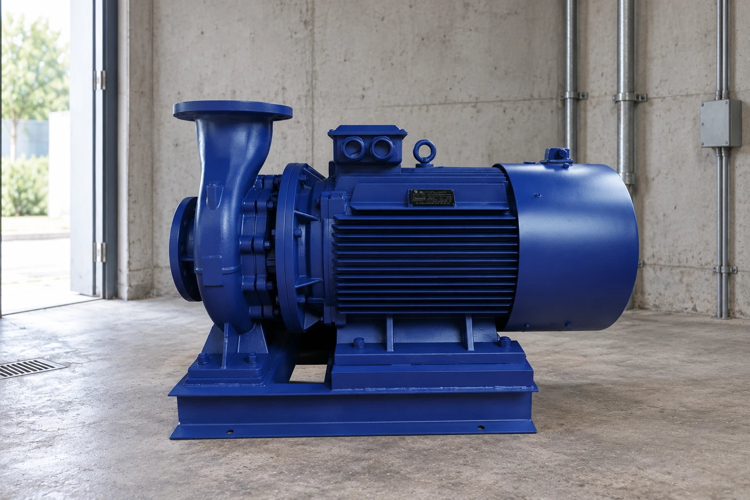
Check location and adjacent contact risks
Record the ring’s specified location relative to the drawing datums. Inspect shoulders, recesses and adjacent features that control its position. Evidence of rubbing on a neighbouring component requires investigation even if the retention device appears intact. The task is to establish why the ring occupies its current position and whether that position meets the design requirements.
Do not infer axial acceptance from a normal-looking running gap at one accessible point. Likewise, a ring that cannot be moved by hand has not necessarily passed the required dimensional and locking checks. Compare the actual arrangement with the drawing, including any required orientation. Where the ring or support has a damaged datum, obtain an approved measurement or repair method before reporting a final position. Record inaccessible areas and the examination limits honestly rather than allowing a photograph to imply complete inspection.
Decide between replacement and an approved repair
Classify the assembly as accepted against named requirements, replacement required or held for engineering review. Attach the observations and measurements that support that classification. If movement has occurred, the repair proposal should address the seat and retention mechanism together. Simply restoring the original gap may leave the reason for movement unresolved.
Changes to material, fit, locking arrangement or support geometry require a documented engineering decision. Do not substitute welding, adhesive, peening or improvised screws as a general remedy. A repair quotation should identify the proposed work, inspection method and acceptance criteria before machining starts. For replacement purchasing, provide serial number, ring location, current dimensions, material information and any previous repair sizes. State when the original specification is unknown. A copied part can reproduce wear or a previous incorrect repair just as readily as the intended design.
Reassemble and verify the complete relationship
Use the approved assembly sequence for the actual materials and retention system. Account for every temporary handling aid and locking component. Record the final ring position, specified locking checks and running clearance as separate results. Where reassembly affects rotor checks, complete those checks under the equipment procedure rather than assuming that a locally accepted ring guarantees the whole rotor assembly.
The IS clean-water centrifugal pump family is a relevant starting point for an equipment inquiry, but its public product images do not identify a specific installed ring arrangement. Request the serial-specific section and parts data. This subject also complements impeller balancing, because changing rotating parts can create additional assembly verification requirements. Neither a balancing result nor a satisfactory clearance measurement replaces the retention acceptance record.
Close the cause investigation and handover
Preserve information about previous vibration, contact, process changes and repair history. These observations may help the responsible engineer investigate movement, but do not assign a single cause solely from damaged locking hardware. A broken component can be a consequence as well as an initiating fault. Separate confirmed findings from the proposed explanation in the report.
The handover should identify the ring and support, drawing revision, as-found evidence, measured condition, repair approval, replacement references and final assembly checks. Name unresolved restrictions and the release authority. Retain rejected parts where the job requires investigation. This record helps the next maintenance team distinguish a properly documented repair from an undocumented change in ring size or retention design. It also gives purchasing the information needed to obtain a compatible spare instead of ordering solely by the most convenient measured diameter.
Further learning: how fits are specified
The IIT Kanpur NPTEL lesson below explains the relationship between nominal dimensions and controlled fits. It provides useful background for reading a ring-and-seat drawing. It does not prescribe a pump wear-ring interference or authorize a repair; those requirements must come from the actual equipment documents.
Frequently asked questions
Does acceptable running clearance prove retention is good?
No. Clearance and retention answer different questions. Check the mounting seat, locating features and specified locking arrangement even when the measured running gap appears to meet the drawing.
Can a loose ring simply be secured with adhesive?
Only an approved repair design can establish an acceptable method. Identify why the ring moved, inspect the support and obtain a documented disposition before changing the retention arrangement.
Does every centrifugal pump have replaceable wear rings?
No. Confirm the actual construction from the sectional drawing. An integral machined surface or another restriction should not be treated as a removable ring merely because its outline looks similar.
Is the ring alone enough for a replacement inquiry?
Include the supporting seat information, equipment identity, location and repair history. A replacement must suit the accepted assembly, including any approved previous machining, rather than simply duplicate a worn component.
What should the final inspection record distinguish?
Record mounting condition, locking acceptance, installed position and running clearance separately. Attach the applicable requirements and identify who released any repair or deviation before returning the pump to service.