
Pump shaft shoulder inspection examines the contact faces and transitions that locate bearings or other shaft-mounted components axially. Check the shoulder, its mating ring or spacer, and the drawing-defined geometry together. A shaft journal can meet its diameter requirement while a damaged abutment prevents correct seating. Record evidence of impact, fretting, corrosion and uneven contact before deciding whether the shaft can be reused. This guide concerns shoulder condition and axial locating surfaces; it does not replace shaft straightness measurement, bearing-seat fit inspection or the approved assembly procedure. All acceptance limits and repair dimensions must come from the actual equipment documentation.
Identify which surface carries the locating function
Start with a sectional drawing and establish which component bears against each shaft shoulder. A visible diameter step may locate a bearing, sleeve, spacer or another part, and different surfaces may have different requirements. Record the shaft part number, pump serial number, assembly location and drawing revision. Label the inspection photographs so the reviewer can identify the drive end and the component side.
Do not infer the load path solely from a loose collection of dismantled parts. A missing spacer or an incorrectly oriented component can create a misleading apparent shoulder contact. Compare the complete assembly with the parts list before interpreting the marks. If the equipment has been repaired, check for approved changes in dimensions or component selection. Establishing the intended locating arrangement is the first step toward distinguishing normal contact from damage or previous incorrect assembly.
Preserve the as-found stack and contact evidence
Plan dismantling so that component orientation and order remain traceable. Photograph the shoulder and mating faces before abrasive cleaning. Record staining, debris, polished patches, impact marks and any gap or unusual contact discovered during removal. Keep bearings, spacers and retaining parts labelled even when they are destined for replacement; their condition can help explain what contacted the shoulder.
Safe dismantling requires the site isolation plan, suitable handling and control of stored energy. The HSE maintenance guidance supplies general UK context, rather than a removal method for this shaft. Do not use an improvised puller or hammering arrangement that transfers uncontrolled force through a precision abutment. If a removal event creates new damage, record it separately. Otherwise, the repair investigation may mistakenly attribute workshop impact marks to the operating failure.
Clean without changing the reference geometry
Remove deposits using a material-compatible process that preserves the contact face, corner and adjacent journal. The objective is to expose the condition for examination. Uncontrolled polishing can remove local evidence and round the edge before its significance has been assessed. Photograph suspicious areas before and after cleaning and record what process was used.
Inspect for cracks, corrosion, dents, scoring and raised material. Look carefully at the transition between the journal and shoulder because the mating component must accommodate the specified corner geometry. A burr that appears small may obstruct contact, but its removal still needs a controlled method. Do not assume that a bright, smooth-looking face has the correct geometry. Where the available visual examination cannot resolve a suspected flaw, define a suitable further examination through a qualified person and keep the part held until that finding has a disposition.
Examine the mating component as well as the shaft
Inspect the bearing ring, sleeve or spacer face that meets the shoulder. Confirm its identity and orientation, then examine its corner relief and contact surface against the applicable drawing. Damage on one component can explain marks on the other. Replacing a bearing alone does not automatically restore a damaged shaft abutment, and refinishing the shaft alone may leave an incorrect mating component in the assembly.
The OISD pump inspection document supports a broader component-based inspection of shafts, sleeves and rotating parts. Use it as general inspection background; its numerical examples do not become automatic limits for another pump. For this job, record the relevant mating-part requirement explicitly. If the contact arrangement is uncertain, request the original section or a documented engineering review instead of judging fit from whether the component can be pushed onto the journal.
| Area | Evidence to record | Unresolved issue to escalate |
|---|---|---|
| Shoulder face | Contact pattern, dents and corrosion | Loss of a suitable locating surface |
| Corner transition | Visible geometry and damage | Mismatch with mating-part relief |
| Adjacent journal | Surface condition and measured identity | Fit issue that may affect seating |
| Bearing or spacer face | Part reference, orientation and marks | Incorrect or damaged mating component |
| Previous repair | Drawing revision and machining history | Undocumented axial dimension change |
This is a qualitative examination plan. It does not supply a permissible fillet radius, face runout or machining allowance.
Define measurements from meaningful datums
Establish which drawing datums control shoulder location and face geometry. Select a measurement setup suitable for the actual question, such as axial position or face relationship to a defined shaft axis. State the support arrangement, instrument, calibration status, measuring positions and surface preparation in the report. A result without its datum and setup cannot reliably establish the intended geometric condition.
Keep different measurements distinct. A dial indicator reading on a shoulder face is not automatically a shaft-straightness result. Likewise, journal diameter measurements do not prove that an abutment is correctly located. Consult the separate shaft straightness measurement guide when the shaft geometry requires that examination. If the datum itself is damaged, document the limitation and obtain an approved alternate setup. Do not quietly choose a convenient surface and report its result as though it came from the specified reference.
Distinguish local surface damage from a system finding
Classify observations before proposing a repair. Raised metal from handling, widespread contact damage, fretting marks and corrosion may require different investigations. Keep measured facts separate from the suspected mechanism. A witness mark can establish where contact occurred without proving the original cause or the magnitude of operating load.
Review the adjacent bearing fit, retaining arrangement and assembly history where relevant. The bearing-fit inspection guide addresses a separate dimensional interface. Do not combine every finding under the vague label “shaft wear.” If several components show related damage, identify their locations and ask the responsible engineer to assess the relationship. A local repair that makes the face appear clean may fail to address incorrect component order, an unsuitable replacement part or another assembly problem that caused the abnormal contact in the first place.
Control any proposed machining or restoration
Machining a shoulder changes more than surface appearance. It may alter axial location, component seating or the space available elsewhere in the stack. Before work starts, the repair proposal should define the finished dimensions, geometry, surface condition, inspection method and any affected assembly checks. Obtain approval from the appropriate engineering authority.
Do not add a shim, change a spacer or modify a bearing corner as an improvised compensation for material removed from the shaft. Those changes require a considered design decision. If a repair is approved, retain both pre-repair measurements and final inspection results. Record the drawing or disposition revision that authorizes the finished condition. Purchasing and future maintenance must be able to identify the repaired assembly; an undocumented difference from the original shaft can otherwise lead to incompatible replacement components during the next outage.
Reassemble with seating evidence
Use the specified installation tools and sequence for the bearing or other located component. Check that accepted mating surfaces are clean and free of temporary protection materials. Confirm orientation and the required seating verification before finalizing the retaining arrangement. Do not use tightening effort alone as proof that the component has reached its intended location.
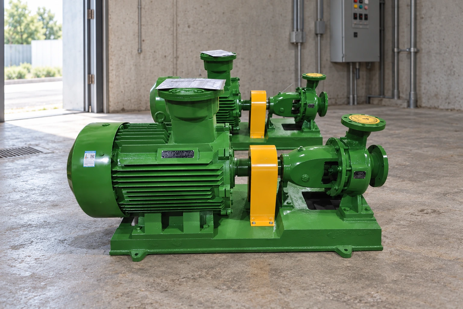
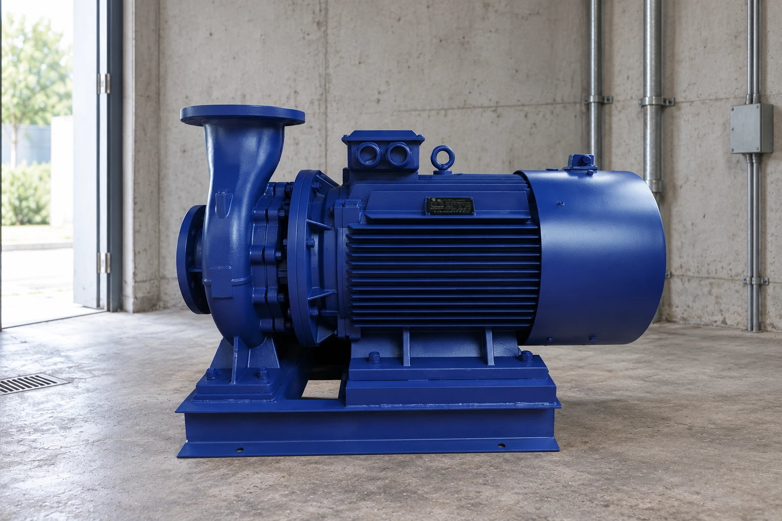
Record the assembly checks required by the equipment procedure, including any axial relationship affected by the shoulder. If a component will not seat as expected, investigate the fit and geometry rather than applying more force. The public IS clean-water pump information can help identify the equipment family, but it does not confirm the detailed bearing arrangement of an individual unit. Request serial-specific instructions. The complete product images accompanying this article are contextual illustrations, not photographs of inspected internal shoulders.
Build a useful release record
The final record should include equipment and shaft identity, component map, as-found photographs, cleaning method, mating-part condition, measurements with datums, accepted criteria and any repair approval. Distinguish accepted, replaced and held components. Name the person who released each unresolved finding and attach the final assembly check rather than leaving it implied by a workshop completion date.
Add this package to the pump maintenance inspection report. A future reviewer should be able to tell whether the shoulder was visually screened, dimensionally measured or subjected to additional examination. That distinction supports better spare-part selection and prevents an old “shaft inspected” note from being used as evidence for checks that were never carried out. Keep limitations, such as inaccessible areas or missing original drawings, visible until they are resolved.
Further learning: limits and fits
The IIT Kanpur NPTEL lesson below explains dimensional limits and fits. It supports reading the relationships between a shaft, bearing and locating surfaces. It is not a shaft-shoulder acceptance standard or a repair demonstration. Use the equipment drawing and approved measurement procedure for the actual inspection.
Frequently asked questions
Is a good bearing-seat diameter enough to accept a shoulder?
No. The diameter and the abutment serve different functions. The shoulder still needs its own condition and drawing-based geometry assessment, together with the component that seats against it.
Can the face simply be polished until marks disappear?
Uncontrolled polishing may change geometry and erase evidence. Record the defect first, then use an approved cleaning or repair method with defined final acceptance requirements.
Does a shoulder-face indicator reading prove shaft straightness?
No. The result depends on its datum, support arrangement and measured feature. Straightness and face-related measurements require distinct setups and must be reported as the checks actually performed.
Is adding a shim a routine repair?
No. Changing the axial stack can affect other component relationships. Obtain an approved repair disposition before changing a spacer, adding compensation or machining a locating face.
What information should accompany a replacement-shaft inquiry?
Supply serial number, part reference, controlled drawing, mating-component details, inspection findings and previous repair history. Clearly distinguish verified dimensions from estimates taken from a worn or damaged shaft.