
A fire pump house layout must protect reliable operation and give safe access to every pump, driver, controller, valve, gauge, battery, fuel, cooling, exhaust, and test component. Begin with the hydraulic arrangement and listed equipment dimensions, then reserve removal paths, working clearances, ventilation airflow, drainage, structural loads, pipe supports, electrical separation, lighting, heating, and fire-rated boundaries required by the project. A compact layout that cannot be tested or maintained is not an acceptable space-saving solution. Keep the calculation and acceptance record with the final project documents so future tests use the same basis.
Sicherheit und Geltungsbereich: Feuerlöschpumpen und deren Antriebe sind lebensrettende Einrichtungen. Arbeiten an Hydraulik, Elektrik, Diesel, Kraftstoff, Batterie, Druck, rotierenden Geräten, Prüfungen und Betriebsstörungen müssen dem aktuellen genehmigten Entwurf, den Herstelleranweisungen, den geltenden Normen und der zuständigen Behörde entsprechen. Dieser Leitfaden erläutert den ingenieurtechnischen Entscheidungsweg; er berechtigt nicht zu Änderungen vor Ort, Umgehungen oder zum Betrieb durch unqualifiziertes Personal.
Arrange the hydraulic path first
Keep suction routes direct, avoid air traps, support pipe independently, place valves in the approved sequence, and leave space for gauges, test lines, and relief discharge. Treat this as a system condition rather than an isolated component choice. Identify the source of every input, the unit used, the operating condition it represents, and the person responsible for approval. If information is preliminary, mark the assumption and test how the decision changes at a conservative boundary. This prevents a neat calculation from hiding an uncertain water level, pressure, valve position, driver condition, or simultaneous demand.
For fire pump house layout, verify this section against the selected pump curve, the actual site arrangement, manufacturer instructions, and the current requirements accepted by the authority having jurisdiction. Check the installed condition as well as the drawing because pipe routes, elevations, supports, controls, and access often change during construction. Record the result in a form that can be repeated during commissioning and later inspection. Do not change a safety-critical setting or isolate fire protection without the approved impairment and restoration process.
Reserve equipment clearances
Use actual vendor drawings for doors, panels, radiator cores, batteries, filters, couplings, glands, bearings, and components that require removal. The most useful evidence is measured or approved project data, not a copied rule of thumb. Identify the source of every input, the unit used, the operating condition it represents, and the person responsible for approval. If information is preliminary, mark the assumption and test how the decision changes at a conservative boundary. This prevents a neat calculation from hiding an uncertain water level, pressure, valve position, driver condition, or simultaneous demand.
For fire pump house layout, verify this section against the selected pump curve, the actual site arrangement, manufacturer instructions, and the current requirements accepted by the authority having jurisdiction. Check the installed condition as well as the drawing because pipe routes, elevations, supports, controls, and access often change during construction. Record the result in a form that can be repeated during commissioning and later inspection. Do not change a safety-critical setting or isolate fire protection without the approved impairment and restoration process.
Provide lifting and replacement routes
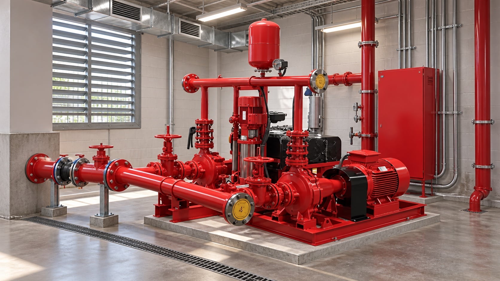
Confirm the heaviest maintenance lift, overhead clearance, anchor points, doorway, turning radius, floor capacity, and route to the exterior. Review this condition at normal, test, and credible abnormal states before procurement. Identify the source of every input, the unit used, the operating condition it represents, and the person responsible for approval. If information is preliminary, mark the assumption and test how the decision changes at a conservative boundary. This prevents a neat calculation from hiding an uncertain water level, pressure, valve position, driver condition, or simultaneous demand.
For fire pump house layout, verify this section against the selected pump curve, the actual site arrangement, manufacturer instructions, and the current requirements accepted by the authority having jurisdiction. Check the installed condition as well as the drawing because pipe routes, elevations, supports, controls, and access often change during construction. Record the result in a form that can be repeated during commissioning and later inspection. Do not change a safety-critical setting or isolate fire protection without the approved impairment and restoration process.
Coordinate ventilation and exhaust
Place intake and discharge so air does not short-circuit. Protect diesel exhaust, radiator discharge, louvers, heating, and freeze-sensitive equipment. The design team should turn this point into a traceable calculation or drawing note. Identify the source of every input, the unit used, the operating condition it represents, and the person responsible for approval. If information is preliminary, mark the assumption and test how the decision changes at a conservative boundary. This prevents a neat calculation from hiding an uncertain water level, pressure, valve position, driver condition, or simultaneous demand.
For fire pump house layout, verify this section against the selected pump curve, the actual site arrangement, manufacturer instructions, and the current requirements accepted by the authority having jurisdiction. Check the installed condition as well as the drawing because pipe routes, elevations, supports, controls, and access often change during construction. Record the result in a form that can be repeated during commissioning and later inspection. Do not change a safety-critical setting or isolate fire protection without the approved impairment and restoration process.
Praktische Entscheidungstabelle
| Layout zone | Space must support | Beweis |
|---|---|---|
| Pump and coupling | Inspection, guard removal, alignment | Vendor maintenance envelope |
| Controller | Door opening and electrical work | Listed clearance and code review |
| Dieselmotor | Cooling, exhaust, fuel, batteries | Engine package drawings |
| Valves and gauges | Operation and replacement | Accessible piping model |
| Test equipment | Full-flow measurement and discharge | Approved test plan |
| Removal path | Largest component replacement | Lift and route study |
| Drainage | Leaks, tests, and room protection | Floor and discharge design |
Control water and drainage
Grade or curb floors as appropriate, route drains to an approved destination, protect electrical equipment, and plan for seal leakage, testing, and sprinkler discharge. Treat this as a system condition rather than an isolated component choice. Identify the source of every input, the unit used, the operating condition it represents, and the person responsible for approval. If information is preliminary, mark the assumption and test how the decision changes at a conservative boundary. This prevents a neat calculation from hiding an uncertain water level, pressure, valve position, driver condition, or simultaneous demand.
For fire pump house layout, verify this section against the selected pump curve, the actual site arrangement, manufacturer instructions, and the current requirements accepted by the authority having jurisdiction. Check the installed condition as well as the drawing because pipe routes, elevations, supports, controls, and access often change during construction. Record the result in a form that can be repeated during commissioning and later inspection. Do not change a safety-critical setting or isolate fire protection without the approved impairment and restoration process.
Separate electrical and fuel hazards
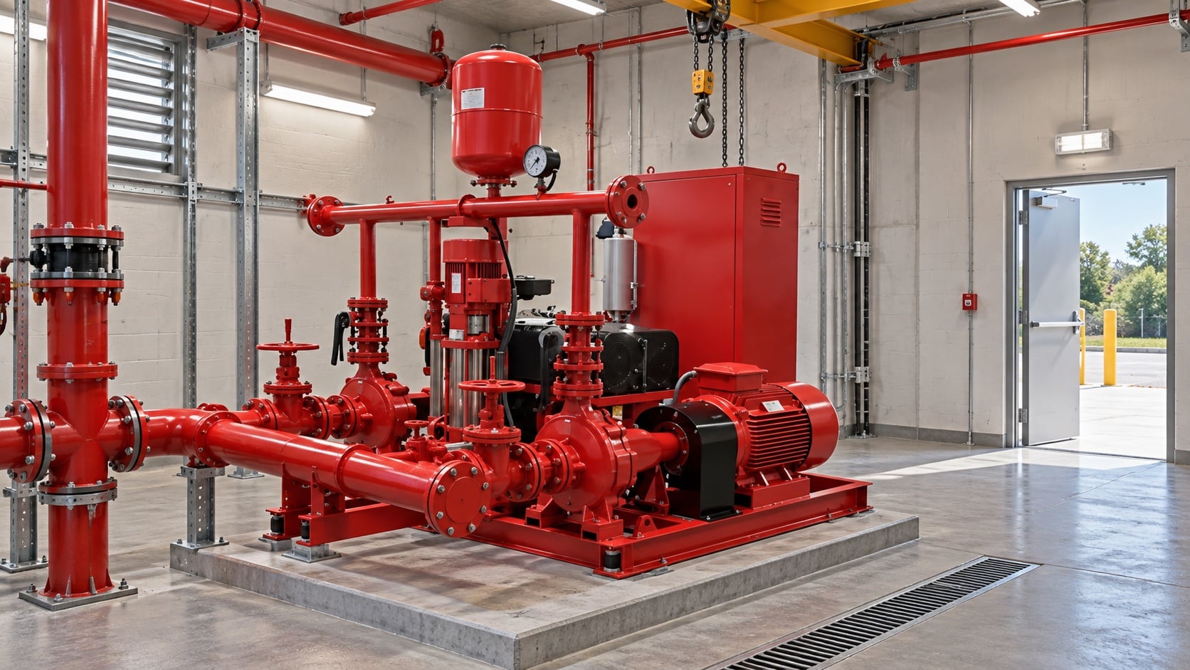
Coordinate controllers, disconnects where applicable, cable routes, lighting, batteries, day tanks, fill and vent pipes, spill control, and ignition sources. The most useful evidence is measured or approved project data, not a copied rule of thumb. Identify the source of every input, the unit used, the operating condition it represents, and the person responsible for approval. If information is preliminary, mark the assumption and test how the decision changes at a conservative boundary. This prevents a neat calculation from hiding an uncertain water level, pressure, valve position, driver condition, or simultaneous demand.
For fire pump house layout, verify this section against the selected pump curve, the actual site arrangement, manufacturer instructions, and the current requirements accepted by the authority having jurisdiction. Check the installed condition as well as the drawing because pipe routes, elevations, supports, controls, and access often change during construction. Record the result in a form that can be repeated during commissioning and later inspection. Do not change a safety-critical setting or isolate fire protection without the approved impairment and restoration process.
Protect access and security
Provide safe stairs, doors, lighting, signage, remote access considerations, flood protection, and controlled entry without delaying emergency response. Review this condition at normal, test, and credible abnormal states before procurement. Identify the source of every input, the unit used, the operating condition it represents, and the person responsible for approval. If information is preliminary, mark the assumption and test how the decision changes at a conservative boundary. This prevents a neat calculation from hiding an uncertain water level, pressure, valve position, driver condition, or simultaneous demand.
For fire pump house layout, verify this section against the selected pump curve, the actual site arrangement, manufacturer instructions, and the current requirements accepted by the authority having jurisdiction. Check the installed condition as well as the drawing because pipe routes, elevations, supports, controls, and access often change during construction. Record the result in a form that can be repeated during commissioning and later inspection. Do not change a safety-critical setting or isolate fire protection without the approved impairment and restoration process.
Review with operations
Walk through weekly tests, full-flow tests, refueling, battery replacement, radiator cleaning, pump removal, and an impaired-pump scenario before construction. The design team should turn this point into a traceable calculation or drawing note. Identify the source of every input, the unit used, the operating condition it represents, and the person responsible for approval. If information is preliminary, mark the assumption and test how the decision changes at a conservative boundary. This prevents a neat calculation from hiding an uncertain water level, pressure, valve position, driver condition, or simultaneous demand.
For fire pump house layout, verify this section against the selected pump curve, the actual site arrangement, manufacturer instructions, and the current requirements accepted by the authority having jurisdiction. Check the installed condition as well as the drawing because pipe routes, elevations, supports, controls, and access often change during construction. Record the result in a form that can be repeated during commissioning and later inspection. Do not change a safety-critical setting or isolate fire protection without the approved impairment and restoration process.
Wie dies sich auf BORRAPUMP-Ausrüstung bezieht
BORRAPUMP liefert technische Pumpenausrüstung für Wasser- und Brandschutzprojekte. Überprüfen Sie die relevanten BORRAPUMP-Produktkonfiguration als Ausgangspunkt, reichen Sie dann den erforderlichen Volumenstrom, die Förderhöhe, die Wasserquelle, den Antrieb, die Leistung, die Steuerungen, die Baustellenbedingungen, die geltenden Anforderungen, die Stückzahl und den Bestimmungsort ein. Die endgültige Auswahl muss auf der hydraulischen Projektbasis und der genehmigten Einreichung basieren; dieser Leitfaden erhebt keinen Anspruch darauf, dass eine Kataloganordnung für jede Jurisdiktion oder jedes Risiko passt.
Ähnliche BORRAPUMP-Anleitungen
- Auswahl von Feuerlöschpumpen
- Diesel- versus Elektrojahrlöschanlagen
- Auswahl der Feuerlöschpumpen-Einheit
Maßgebliche Referenzen
Die folgenden Quellen legen den Normenbereich, den Brandschutzkontext und die Pumpensystemprinzipien fest, die in diesem Leitfaden verwendet werden. Wenden Sie stets die für das Projekt akzeptierte Ausgabe und lokale Einführung an.
- NFPA 20 Normenentwicklungsseite
- CDC/NIOSH structure fire hazards
- U.S. Fire Administration fire sprinkler training manual
Lernvideo
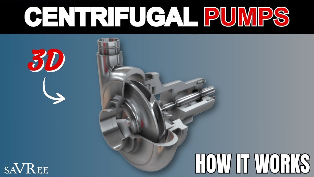
Bildungshintergrund von saVRee: Wie Zentrifugalpumpen funktionieren. Das Video unterstützt das zugrundeliegende ingenieurtechnische Konzept und ersetzt nicht die projektspezifischen Brandschutzanforderungen.
Häufig gestellte Fragen
How much clearance does a fire pump need?
Use applicable requirements and actual manufacturer maintenance envelopes; there is no safe universal clearance for every package.
Can the controller be placed behind piping?
The layout must preserve required working space, visibility, access, and safe maintenance.
Should the pump room have a floor drain?
Plan approved drainage for leaks, testing, and room protection while preventing backflow, freezing, and unsafe discharge.
Why model replacement routes?
A pump, motor, radiator, or controller may need replacement without demolishing critical walls or piping.
Abschließende Prüfliste
Vor der Freigabe sind die hydraulischen Grundlagen, die Wasserquellenbedingungen, die ausgewählte Pumpenkennlinie, die Daten von Antrieb und Steuerung, die Nenndrücke der Komponenten, die Ventilanordnung, das Prüfverfahren, die Zugänglichkeit, die Entwässerung, die Alarme und das Wiederherstellungsverfahren zu bestätigen. Differenzen zwischen den Zeichnungen und dem installierten System sind zu berechnen. Während der Inbetriebnahme sind kalibrierte Instrumente zu verwenden und Saugdruck, Förderdruck, Durchfluss, Drehzahl, Antriebszustand, Alarme und abweichende Beobachtungen an jedem geforderten Punkt aufzuzeichnen. Die akzeptierten Ergebnisse sind bei den Pumpenraumprotokollen aufzubewahren, damit spätere Inspektionen vergleichbare Werte liefern.