Submersible sewage pump sizing starts with the required flow and total dynamic head, then checks wastewater characteristics, the selected pump curve, wet-well cycling and reliability. Horsepower and discharge diameter alone cannot establish whether a pump will work. A useful selection states where the pump must operate, what material it must pass and how the station will respond when inflow changes or equipment fails. This guide is for engineers, contractors and buyers specifying a wastewater lift station. Numerical examples are illustrative calculations, not Borra product ratings or a construction design.
Define the wastewater before calculating the pump
Identify whether the station receives raw domestic sewage, screened wastewater, treated effluent or an industrial mixture. These liquids can have very different solids, fibers, temperature and chemical conditions. Record what reaches the wet well after any upstream screens or treatment, rather than describing every duty as dirty water. A non-clog sewage pump does not automatically become a grinder pump or an abrasive-slurry pump. Product terminology must be supported by the actual supplied impeller and operating limits.
For a replacement station, ask operators about blockage history, unusual deposits and storm-related inflow. A new station needs information about connected fixtures, occupancy, industrial discharge and infiltration allowances specified by the designer. Document the source of each assumption. Treat a missing inflow assessment as an engineering question, not a reason to select a much larger motor. Oversizing can make the station cycle frequently or operate away from the intended hydraulic region.
Das Borra WQ submersible sewage pump is a relevant product family to discuss once the duty is defined. Obtain the proposed model’s curve, confirmed solids passage and installation information before accepting an offer. The general product page does not replace that model-specific evidence.
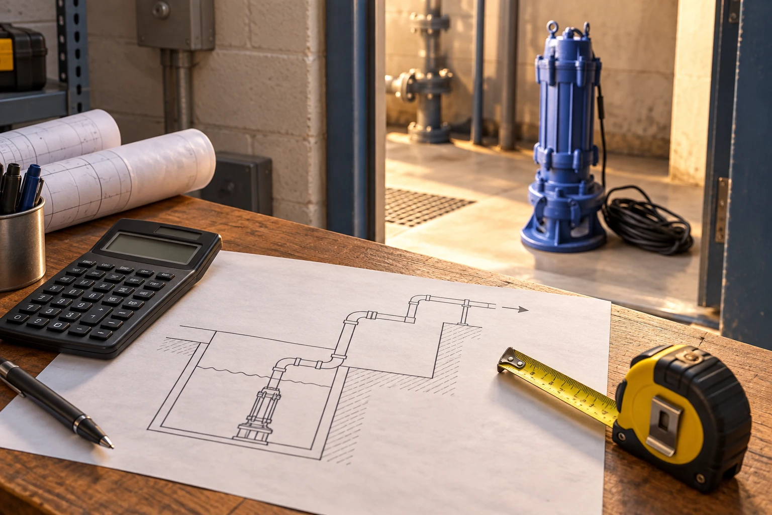
Establish the design flow and operating cases
Separate average inflow, normal operating flow and the design peak. They serve different purposes. Average inflow helps assess cycling and operating cost; peak inflow determines whether the station can keep up; low inflow determines whether the selected control range creates excessive starts or prolonged retention. Include future growth only when its scale and timing are defined. A speculative growth allowance can distort the first years of operation.
Use the applicable local design method for connected sanitary flow and permitted allowances. Existing stations may support an estimate with flowmeter records or a wet-well level trend, but confirm whether those records include rain events and equipment outages. A brief measurement during a quiet hour is not a design peak. Note how inflow was measured and whether a level-to-volume relationship was calibrated.
If two pumps will operate together, do not assume their installed combined flow is twice the single-pump flow. The force main’s resistance increases as flow increases. Combine the pump curves at a common head and intersect the result with the system curve. For the control sequence, see duplex sewage pump control.
Calculate total dynamic head at the proposed flow
Total dynamic head includes the difference in liquid elevation, friction through the force main and local losses through fittings, valves and outlet arrangements. Include pressure at the receiving connection if it is pressurized. Use a consistent datum and identify the wet-well level used. The lowest pumping level often creates more static lift than the highest level, while a receiving sewer or tank may also fluctuate.
For an illustrative open-to-open arrangement, assume 8 m of static lift, 5 m of pipe friction and 2 m of valve and fitting losses at the target flow. The total is 15 m. These assumed losses must be recalculated for the actual pipe bore, length, roughness and fittings. A larger pipe might reduce friction, but the designer must also consider solids transport, route constraints and construction cost. Do not add a universal percentage and call it a verified design margin.
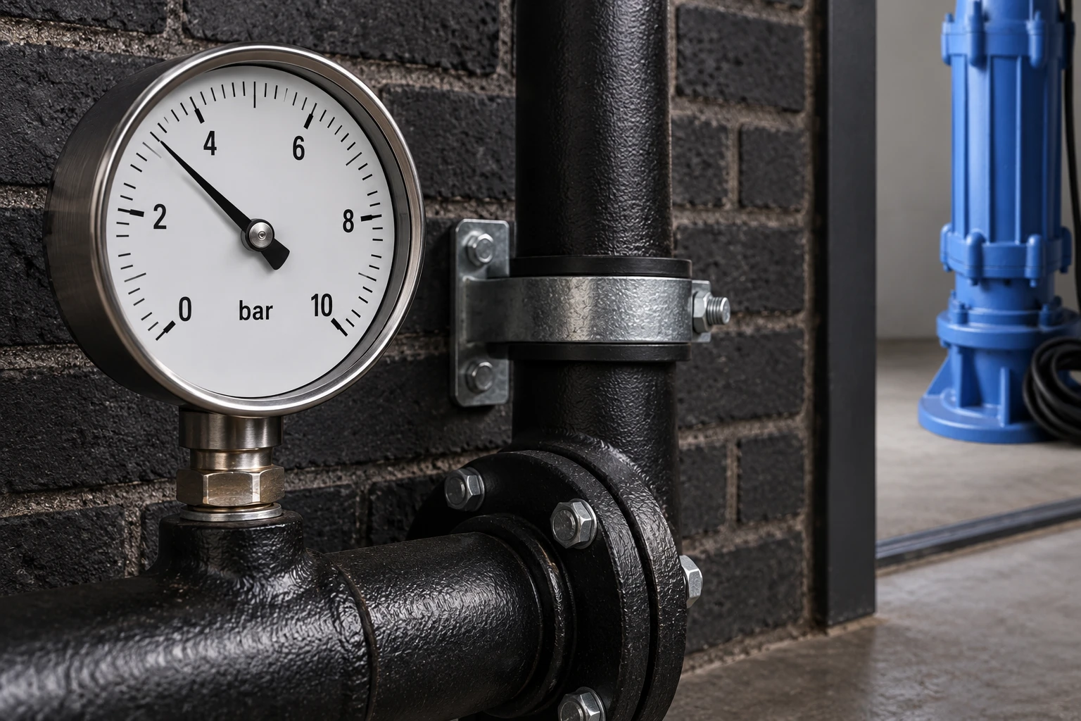
Benutzen what pump head means to distinguish head from pressure. Pressure depends on liquid density; head describes energy per unit weight. Record both where purchasing documents use different units, so a pump offer in metres is not confused with a pressure requirement in bar.
Match the curve rather than the motor nameplate
Find the intersection of the pump and system curves for each important case. Confirm the exact frequency, speed and impeller diameter shown on the offered curve. Review efficiency, input power, allowable operating region and required cooling or submergence. The operating point should remain acceptable as the wet-well level changes and as pipe resistance varies. A nominal flow printed beside a catalogue picture does not describe every possible installation.
Motor selection needs the documented power demand across the permitted operating range, together with the electrical supply and service conditions. Hydraulic power for water is approximately density multiplied by gravitational acceleration, flow and head. That calculation is only the fluid power; losses mean electrical input is higher. Use the manufacturer’s complete selection rather than dividing by an assumed efficiency and claiming a motor size is confirmed.
Das centrifugal pump curve guide explains how the flow, head, efficiency and power traces work together. Use it before comparing offers that state similar horsepower but different operating capabilities.
Check the wet well and start frequency together
The wet well is part of the pump selection. Determine its usable volume between start and stop levels, the pump’s minimum operating level, inlet conditions, emergency storage and maintenance access. An arrangement that meets peak flow can still be unreliable if the normal working volume produces excessive starts. Conversely, unnecessarily large storage can increase retention and create operating problems.
For a simplified constant-inflow example, let usable working volume be V, inflow be q and installed pumping flow be Q, with Q greater than q. Filling time is V/q and pump-down time is V/(Q−q), provided units match. Their sum gives the idealized cycle time. Real inflow and the pump’s installed flow vary, so validate the result against the specified motor start limit and a representative control sequence. This relationship does not set a universal minimum wet-well size.
Level settings must leave room for the independent high-level alarm and the response time needed before overflow. A designer should verify the physical elevations and receiving system. Read sewage pump float-switch placement for the separate control-layout checks.
Use a selection record that suppliers can verify
| Item | Information to record | What to verify in the offer |
|---|---|---|
| Wastewater | Source, solids, fibers, temperature and chemistry | Documented compatibility and passage |
| Erforderlicher Fluss | Normal, peak and low-inflow cases | Installed flow at each duty |
| Head | Static lift and calculated route losses | Matching speed and impeller curve |
| Wet well | Working levels, volume and access | Cooling, submergence and cycling limits |
| Electrical supply | Voltage, phase, frequency and starting method | Motor and control compatibility |
| Zuverlässigkeit | Standby requirement, alarm response and power loss plan | Tested station operating sequence |
This is a qualitative procurement checklist, not a table of product performance. For general station context, the EPA in-plant pump-station fact sheet describes the main system components. The DOE pump-system resources support evaluating the entire pumping system rather than selecting by motor size alone.
Commission against the approved duty
Before commissioning, confirm the supplied model, curve and control schedule match the approved selection. Check that discharge piping has been completed as designed and that valves are correctly configured. Record level, flow and relevant pressure readings while each pump operates alone. Test the combined sequence where applicable, along with alternation, standby response and the independent alarm. Do not infer delivered flow from motor current alone.
Keep a reference record of the station’s initial measured performance. Later increases in runtime may indicate inflow changes, obstruction, wear or a different system condition. A clear baseline makes those causes easier to separate. If the results differ from the selection, investigate the route, operating levels and instrumentation before changing the impeller or control settings.
Distinguish a replacement from a redesign
An unchanged replacement should be checked against the existing approved duty, while a redesign needs its new inflow and route assumptions documented. Mark any changes in connected buildings, force-main length, receiving level or standby requirement. Ask the supplier to identify whether its offer preserves the original operating point or changes it. This prevents a replacement quotation from quietly becoming an unreviewed station redesign. Keep the final selection and measured commissioning duty in the same maintenance file.
Use the wastewater pump types guide as the parent selection overview.
Questions buyers should settle before ordering
Can I select a sewage pump only by horsepower?
No. Horsepower does not establish delivered flow, head or solids suitability. Request the exact pump curve and compare it with the calculated system duty. Electrical supply, control behavior and wastewater conditions must also match.
Does a larger pump prevent every overflow?
No. Overflow can follow a blockage, power failure, failed level signal or inadequate force main as well as insufficient pump capacity. Size the hydraulic duty and design the alarm, standby and response arrangements together.
Should two pumps each handle the full peak flow?
That depends on the governing design requirement and failure case. Do not assume a universal arrangement. State the required capacity with one pump unavailable and have the designer verify the single and combined operating points.
Which documents should accompany a quotation?
Request the selected model, performance curve, solids and liquid limits, electrical data, installation drawing, level requirements and operation manual. Include the flow and head calculation so the supplier can identify any mismatch before delivery.
Weiterbildungen
This EPA educational session covers wastewater operator calculations, including pump flow and wet-well volume. Use it to understand the quantitative checks in this guide; it does not replace the selected station design or device manual.