Noise or vibration from a booster pump can be caused by cavitation, air, poor alignment, loose anchors, pipe strain, an unstable operating point, worn bearings, a damaged coupling, or a control sequence that starts and stops the set too aggressively. A short sound observation is not enough to identify the cause. Record where the vibration is strongest, when it appears, which pump is running, suction and discharge pressure, flow, motor current, and whether the piping or foundation is moving.
Separate hydraulic, mechanical, and structural clues
Hydraulic noise often changes with flow, suction pressure, or valve position. Mechanical vibration may track motor speed and remain when the discharge valve changes. Structural transmission may be stronger at a pipe support, wall, or floor than at the pump casing. A technician should compare the pump, motor, baseplate, flexible connectors, headers, and nearby structure rather than replacing a pump based on sound alone.
El BorraPumps booster-regulator equipment must be installed with the actual suction condition, piping support, foundation, and control sequence in mind. Product images cannot confirm the suitability of a particular base, connector, or motor.
Check cavitation and suction conditions
Cavitation can produce a crackling or gravel-like sound and rapid vibration. Check low inlet pressure, clogged strainers, excessive suction losses, high water temperature, air ingress, or a pump operating above its available suction condition. Compare net positive suction head available with the selected pump’s requirement using project data. Do not throttle a suction valve to quiet a pump; that can worsen the condition.
If the sound appears only at peak demand, record suction pressure while the pump is loaded. If it appears after a tank level drops, check low-level control and the inlet arrangement. Stop and isolate equipment safely before opening a strainer or vessel.
Inspect mounting, alignment, and pipe strain
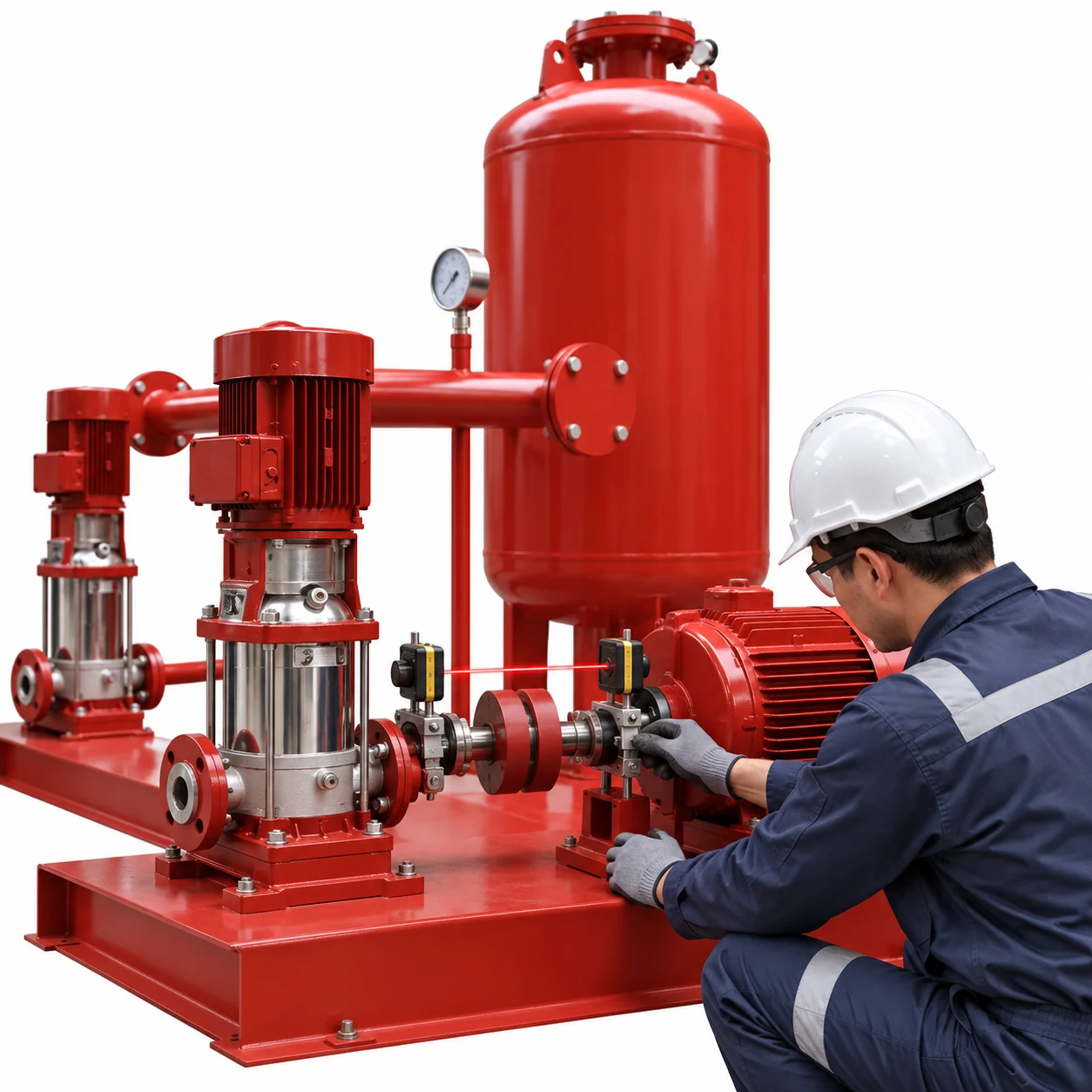
Loose anchor bolts, a soft foot, an uneven base, or a distorted skid can transmit vibration. Check anchor and mounting conditions according to the equipment instructions. Confirm that the pump and motor are aligned after installation and after any pipe work. The generated alignment inspection image shows the type of inspection area to document, not a universal alignment method.
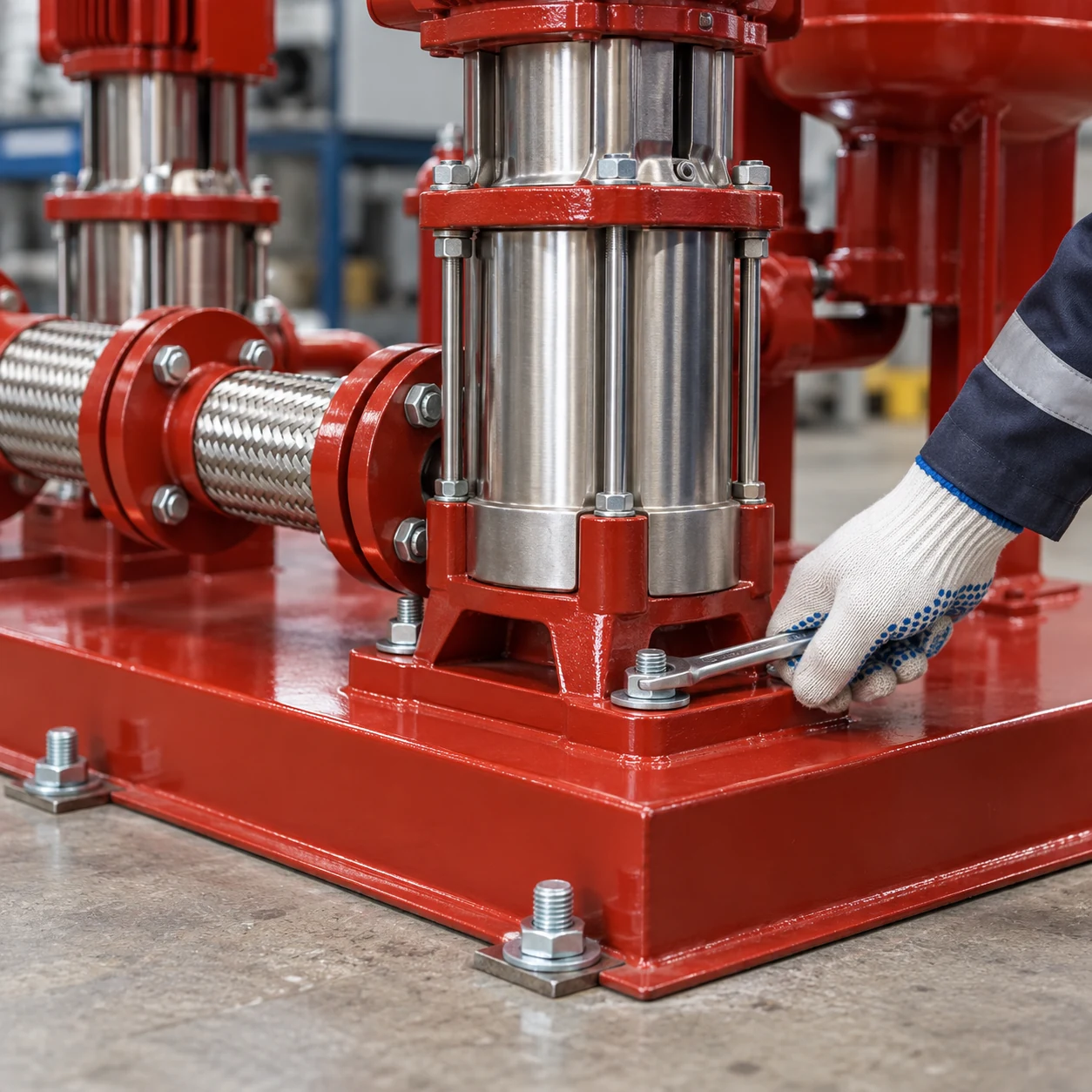
Pipe should be supported independently so its weight and thermal movement are not carried by pump nozzles. Flexible connectors must be selected and installed for the pressure, movement, and alignment they are expected to accommodate. A connector that is stretched, compressed, or misaligned can amplify vibration rather than absorb it.
| Hallazgo | Likely direction | Useful check |
|---|---|---|
| Crackling noise at high flow | Cavitation or air | Suction pressure, strainer, inlet joints |
| Vibration at motor and coupling | Alignment, bearing, coupling | Alignment record, bearing condition, soft foot |
| Vibration at pipe support | Pipe strain or inadequate support | Check supports and nozzle loads |
| Pulsation during staging | Control or check-valve transition | Trend pressure and pump states |
| Vibration after maintenance | Loose anchor or disturbed alignment | Compare baseline and torque/fit records |
| Noise at low demand | Near-shutoff operation or cycling | Minimum flow, vessel, and control settings |
These are diagnostic directions, not permission to operate unsafe equipment.
Check the pump operating point
A centrifugal pump operating near shutoff or far from its preferred range can generate recirculation, heat, and vibration. Compare measured flow and head with the supplier’s curve. Review whether one pump is oversized, whether two pumps are operating in parallel at a poor point, and whether a VFD has been limited to an unsuitable speed. The VFD selection guide explains why minimum speed, motor cooling, and pressure feedback are connected.
Short cycling can also create repeated mechanical shocks. The booster pump cycling guide provides a method for checking the pressure vessel, sensor, leaks, and staging.
Inspect bearings, seals, and coupling
Follow the manufacturer’s maintenance schedule for lubrication, bearing temperature, seals, coupling elements, and motor cooling. Look for abnormal heat, grease leakage, shaft movement, damaged elastomer, or a seal leak that has reached a bearing. Do not use a hand as a vibration instrument near rotating equipment. Use calibrated instruments and keep guards in place.
Trend vibration at repeatable points and operating conditions. A single number is less useful than a baseline showing when the trend changed. Escalate a rapidly rising trend, excessive temperature, rubbing, or a safety concern to the responsible maintenance engineer.
Correct controls and check valves
Check-valve slam, rapid ramping, or poor staging can transmit pressure pulses to the skid. Verify the valve type, orientation, closing behavior, and control sequence. A sensor mounted in a turbulent location can also create hunting that appears mechanical. The pressure sensor placement guide explains how the signal point affects control stability.
Commission and document the repair
After correction, record suction and discharge pressure, flow, speed, current, vibration measurement points, temperature, active pump, valve positions, and control settings. Repeat low, normal, and peak-demand tests. Check that the vibration does not move into the piping or building structure. Keep photographs and an updated baseline for future technicians.
Establish a baseline before replacing parts
Take baseline measurements after a successful commissioning test. Use the same sensor locations, speed, flow, and operating pumps on future inspections. Photograph the coupling guard, flexible connectors, anchors, and pipe supports. A baseline lets the team distinguish a gradual bearing trend from a sudden pipe-support problem and reduces unnecessary part replacement.
Coordinate mechanical and hydraulic fixes
A mechanical repair can change the hydraulic response, and a control change can alter vibration. After tightening anchors, replacing a check valve, changing a drive ramp, or moving a sensor, repeat the complete operating test. Confirm that the fix did not move the vibration to the header or create a new pressure transient.
Check the installation after any pipe change
Adding a branch, changing a valve, replacing a flexible connector, or moving a support can alter both hydraulic loss and structural response. Confirm that the pump nozzles are not being pulled into alignment by the pipe. Check that guides allow the intended movement and that anchors transfer loads to the structure. Repeat the vibration baseline after the work, even if the pump itself was untouched.
If several pumps are connected to one header, compare each pump separately and then observe the combined operation. A check valve that behaves acceptably with one pump may chatter when two pumps run in parallel. The control sequence, pipe support, and valve selection must be evaluated together.
Protect people while testing
Keep guards installed, respect lockout and depressurization procedures, and avoid reaching near rotating shafts or pressurized flanges. Use an approved vibration instrument and follow the site’s permit and access rules. A quiet pump is not a successful result if the test was performed unsafely.
Use operating data, not sound alone
Sound travels through floors and pipes, so the loudest location may not be the source. Compare readings at the pump casing, motor, base, header, and nearby structure while changing one operating condition. Note whether the symptom follows the pump, the speed, or the pipe path. This simple separation often prevents a good pump from being replaced for a support or valve problem.
Close the loop with the owner
Explain the observed cause, the correction, the remaining operating limit, and the next inspection date. An owner who knows the trigger can report a change early instead of waiting for a seal, bearing, or pipe support to fail.
Record the operating condition
Write down whether the pump was starting, stopping, staging, or running steadily when the symptom appeared. The same sound can have different causes at different states, and a useful record makes the next inspection faster. Include the pump speed and whether nearby fixtures were open today.
Agree on the next review
Set a follow-up date and repeat the baseline under the same operating conditions. Early review after a correction can reveal a returning bearing trend, loose anchor, or changed control sequence before the symptom becomes a shutdown.
Engineering sources
El US Department of Energy pump-systems resources y Purdue University fluid-mechanics material provide background on pump operating conditions and fluid behavior. Equipment limits and the site’s safety procedures remain controlling.
Preguntas frecuentes
Is any vibration from a booster pump normal?
All rotating equipment has some vibration, but the acceptable level depends on the equipment, installation, measurement method, and manufacturer limits. A new or rising trend requires investigation.
Can a flexible connector fix vibration by itself?
No. It may reduce transmission when correctly selected, but it cannot fix cavitation, misalignment, loose anchors, pipe strain, or a poor operating point.
Why is noise worse at low demand?
The pump may be near shutoff, cycling, or operating with insufficient useful flow. Check minimum-flow requirements, vessel drawdown, control band, and the pump curve.
What should be measured during diagnosis?
Record location-specific vibration, sound observation, suction and discharge pressure, flow, motor current, speed, temperature, pump state, and the condition that makes the symptom appear.
Further learning
The NPTEL IIT Kharagpur lecture on pump characteristic curves is useful background for understanding why the installed system can behave differently from a catalogue point. It is educational material, not a substitute for the selected pump manual, project calculations, or local code review.