
Pump shaft alignment methods range from a straightedge check to dial indicators and laser instruments. For a separately coupled pump and motor, choose a method that can measure both shaft offset and angularity, resolve the specified tolerance, and produce repeatable results. A straightedge can help with initial positioning but should not automatically become the final acceptance method. Alignment also depends on stable supports, suitable shims, controlled pipe loads and any approved thermal targets. The task is complete when the final secured assembly meets its documented requirements, rather than when an instrument briefly displays an acceptable result.
This guide compares measurement methods for general industrial water-pump assemblies. It does not replace a model-specific installation manual or set acceptance values for fire pumps. Begin by confirming whether your machine has a field-adjustable coupling; a close-coupled assembly may need a different inspection process.
Define the assembly and the alignment target
Identify the pump, driver, coupling, operating speed and arrangement from the equipment documents. Mark which machine will remain fixed and which can be moved. Establish the permitted horizontal and vertical movement, available shim space and access for instruments. A method that works well on an open workshop skid may be impractical beside fixed pipework in a crowded plant room.
Obtain the applicable cold alignment target and final tolerance before taking readings. Coupling movement capability is not automatically an acceptable machinery alignment tolerance. Similarly, an instrument’s default tolerance table must be checked against the approved project requirements. If thermal movement is significant, the specified cold position may intentionally differ from the operating position. Do not invent a compensation value from temperature alone.
Nuestros close-coupled versus frame-mounted pump guide explains why maintenance access and adjustment responsibilities differ between assemblies. For a product discussion, provide the actual configuration when reviewing an Bombas centrífugas de agua limpia de IS. The product family name alone does not establish the coupling or alignment procedure supplied with a particular order.
Separate offset from angular misalignment
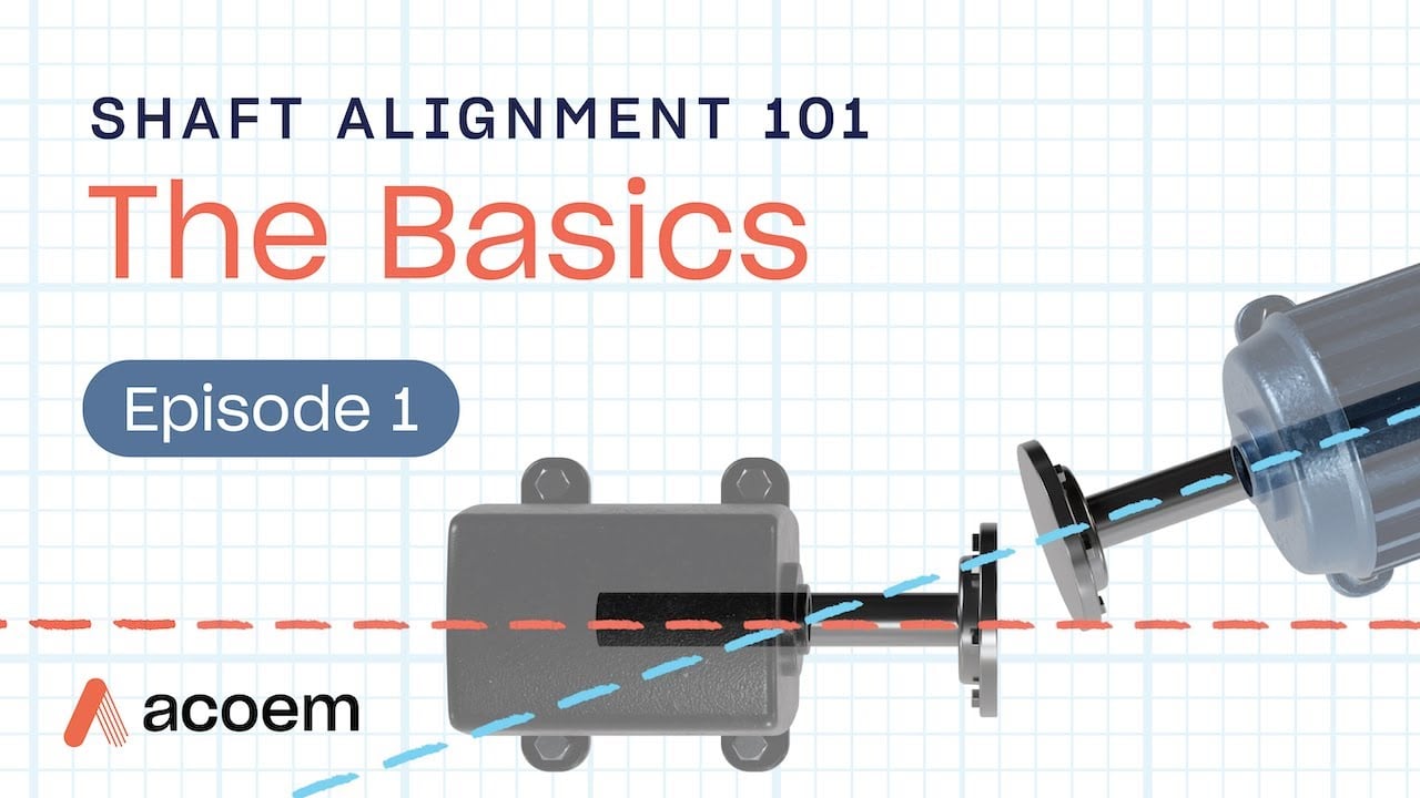
Offset means the shaft centerlines are displaced at the reference location. Angularity means their directions differ. An installation can have both at the same time, independently in the horizontal and vertical planes. Measuring only the separation between coupling rims does not fully describe this geometry.
Use an agreed reference plane and sign convention so that readings can be understood by the next technician. Record distances between measuring planes and the movable machine’s feet. These dimensions affect calculated corrections; measuring from a convenient guard edge instead of the required plane can produce a convincing but incorrect movement instruction.
Also distinguish shaft alignment from coupling condition. Damaged hubs, excessive runout, loose fits and worn flexible elements need their own assessment. Moving a motor cannot repair an eccentric hub. Check mechanical integrity before accepting alignment readings as reliable evidence of shaft position.
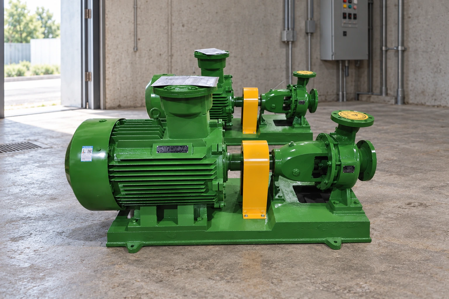
Straightedge and feeler gauges: useful for rough positioning
A straightedge across suitable coupling surfaces can help bring a machine into an initial position. Feeler gauges may reveal changes in the coupling-face gap. These checks are inexpensive, quick and useful before installing more precise instruments, particularly after replacing a driver or setting a new skid.
Their limitations matter. The reference surfaces may not be concentric or square to the shaft axes. Access can restrict where measurements are taken, and the tool may not resolve the final requirement. A small apparent gap does not establish the condition in both measurement planes. Treat rough positioning as a preparation step unless the approved equipment instructions explicitly permit it for final acceptance.
Avoid describing a pump as precision-aligned simply because the coupling rims look even. Record the actual method and its limitations. If the required acceptance cannot be demonstrated with the available equipment, arrange a suitable measurement method before commissioning rather than substituting an unsupported judgment.
Dial indicators: measure carefully and control setup error
Rim-and-face and reverse-dial methods use different measurement arrangements. Select the procedure suited to the coupling, shaft access and required accuracy. Confirm that indicator travel, contact surfaces and bracket rigidity are appropriate before rotating the assembly under the approved isolation procedure.
Rim-and-face measurements combine radial and face readings; axial movement can influence the face result. Reverse-dial methods compare radial readings at separated planes and depend on correct distances and signs. Follow a validated calculation procedure rather than mixing formulas from two different arrangements. Preserve the original readings alongside the calculated foot corrections so another person can check the result.
Bracket sag, loose magnetic bases, rough surfaces and inconsistent rotation positions can dominate the measured error. Check the setup as instructed, repeat a measurement cycle, and investigate poor repeatability before moving the motor. A dial indication with many decimal places is not evidence of accuracy if the mounting moves between readings.
Laser alignment: faster calculations with the same physical responsibilities
Laser tools can simplify geometric calculations, display both offset and angularity, and guide machine movements. They can also save measurement reports, which helps handover and repeat inspections. However, the operator still has to enter the correct machine dimensions and targets, mount the sensors securely and choose the correct measurement program.
Follow the instrument instructions for rotation range, coupling state and measurement collection. Reflective surfaces, blocked beam paths, loose brackets or unstable machine supports can undermine results. If repeated readings vary substantially without a machine movement, correct the setup before relying on a calculated shim change.
Fluke’s pump alignment explanation describes the principal methods and preparation considerations. Use such guidance to understand measurement choices; the pump, coupling and project documents still determine the acceptance target. A laser tool measures the condition presented to it, including any errors introduced by the installation.
Compare methods against the actual job
The following decision table concerns measurement capability and preparation, not universal accuracy rankings. A well-controlled dial procedure can be more useful than a poorly mounted laser system. The comparison follows the method distinctions discussed in the Fluke reference above.
| Método | Useful role | Main setup risks | Evidence to retain |
|---|---|---|---|
| Straightedge and feeler gauges | Initial positioning and gross-error checks | Unsuitable coupling surfaces; incomplete geometry | Check locations and reason final acceptance is permitted or deferred |
| Rim-and-face dial indicators | Quantitative alignment with accessible reference surfaces | Axial movement, bracket sag and sign errors | Original readings, dimensions and calculation sheet |
| Reverse-dial indicators | Quantitative comparison of shaft positions at separated planes | Bracket rigidity, incorrect distances and inconsistent rotation | Sag assessment, repeated readings and foot corrections |
| Laser instruments | Guided measurement, correction and reporting | Incorrect dimensions, loose mounts and unapproved targets | Instrument setup, target source and final saved report |
Select the method before mobilizing the maintenance team. Include required training, access arrangements and calibration status in the work preparation. If rotation is constrained, confirm that the selected instrument and procedure support the available movement; do not simply omit the inaccessible readings.
Correct soft foot and external forces before chasing readings
Soft foot occurs when the support condition distorts the machine as its bolts are tightened. Causes can include uneven supports, unsuitable shims, dirt or external forces. Inspect contact surfaces and follow the equipment procedure to identify and correct the condition. Adding shims randomly can hide a problem temporarily while introducing a new one.
Use clean, suitable shims with proper support beneath the foot. Avoid excessive stacks and partly supported pieces. Tighten hold-down bolts using the specified sequence and repeat the measurement. If the reading changes significantly after tightening, the final secured machine is the condition that must be resolved.
Pipe connections can also move the casing. The inline pump installation guide addresses support and flange-fit checks. A separately coupled installation needs its own alignment procedure, but the principle remains useful: pipework should not be forced into position with flange bolts. Investigate changing readings after pipe connection instead of moving the motor repeatedly to compensate for unresolved strain.
Make corrections in a controlled sequence
Complete the approved isolation, pressure release and access preparation before removing guards or touching the coupling. Only qualified personnel should perform the work. Control all relevant energy sources, including any possibility of reverse rotation or automatic starting, using the site’s equipment-specific procedure.
Take and save the initial measurements. Calculate vertical corrections, inspect the existing shim arrangement and make deliberate changes. Then address horizontal movement with suitable adjustment provisions. Follow the instrument or validated dial procedure for the correction order. Keep the fixed reference machine fixed unless engineering approval requires a different approach.
After each significant adjustment, secure the machine as required and repeat the measurement. Do not force movement against tight bolts or use pipework as a lever. If the machine becomes bolt-bound or base-bound, stop and resolve the installation constraint. Enlarging holes or modifying supports requires an approved repair decision, not an improvised alignment shortcut.
Verify after tightening and during a controlled return to service
The final report should identify the measurement method, dimensions, target source, final readings, bolt condition and relevant installation state. Note whether pipework was connected and whether the required cold condition was established. A saved report without these details can be difficult to interpret during the next outage.
Refit guards and complete the approved startup checks before operation. Compare vibration, bearing temperature and other relevant observations under repeatable operating conditions. The pump vibration measurement guide explains how to build comparable records. Vibration is supporting evidence; a quiet machine does not replace a documented geometric alignment check.
El Libro de referencia sobre sistemas de bombeo del Departamento de Energía de los Estados Unidos places maintenance within overall system performance. Retain hydraulic operating data as well as mechanical records, since cavitation, off-design operation and looseness can create symptoms that persist after alignment. Escalate unexplained changes with evidence rather than assuming the first suspected cause was correct.
Formación continua
The accompanying ACOEM educational video introduces shaft alignment geometry. It helps explain what the measurements represent; it is not a model-specific tolerance or authorization to operate machinery without guards. Use the written inspection and handover requirements above to prepare the actual work.
Preguntas frecuentes
Is laser alignment always required for a pump?
No. The selected method must be suitable for the assembly and demonstrate the approved tolerance. Instrument access, repeatability and the quality of the procedure matter alongside the tool type.
Can a flexible coupling correct shaft misalignment?
A flexible coupling accommodates specified movement, but its capability should not replace the machinery alignment requirement. Obtain the approved target from the relevant equipment and project documents.
Why do alignment readings change after bolts are tightened?
Possible causes include soft foot, unsuitable shims, support movement or external loads. Check the final secured installation and measurement setup before making more corrections.
Should a close-coupled pump be aligned like a separate pump and motor?
Not automatically. Confirm the actual construction and manufacturer’s inspection procedure. Some assemblies do not provide the field adjustments used on separately coupled machines.
What should an alignment service report include?
Include equipment identity, method, dimensions, target source, original and final readings, corrections, support and pipe conditions, and the final secured state. Add operating verification observations after the approved restart.