
Pump head is the mechanical energy a pump adds to a liquid per unit weight, commonly expressed as metres or feet of that liquid. It is not the physical height of the pump and is not identical to pressure. For an incompressible liquid, pressure rise relates to head through density and gravity, so the same head produces different pressure for liquids with different density. Pump selection uses total dynamic head: elevation, pressure, velocity, and friction effects between defined system points at the required flow.
Este artículo es una guía práctica de diagnóstico y adquisición, no un sustituto de las instrucciones del fabricante de la bomba, de un diseño de sistema aprobado, de las normas eléctricas y de fontanería vigentes, ni del servicio técnico cualificado in situ. Aísle la energía y la presión antes de abrir el equipo. Los trabajos en pozos, las maniobras de izaje, los espacios confinados, las aguas residuales, las ubicaciones eléctricas húmedas y las pruebas con energía requieren personal competente y controles específicos para la tarea.
Why engineers use head
Head lets a pump curve describe energy addition with less dependence on liquid density than a pressure-only curve. A centrifugal pump generating a given head on water can show a different pressure rise on a denser or lighter liquid, while required power changes with density and efficiency. Always state the liquid, temperature, and units. Do not convert a nameplate pressure into head without knowing where it was measured and whether it is gauge, differential, or absolute pressure. Vapor pressure and suction conditions require their own consistent reference.
Altura dinámica total
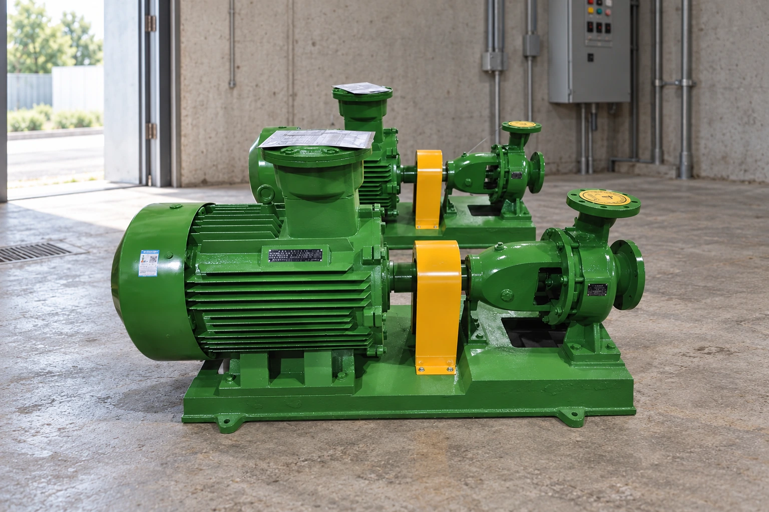
Choose a suction reference point and a discharge reference point. Account for elevation difference, required pressure difference, velocity-head difference when significant, and friction losses through suction and discharge pipes, fittings, valves, filters, heat exchangers, meters, and nozzles. In an open tank-to-open tank system, both surfaces may be at atmospheric pressure, but elevation and friction remain. In a closed or pressurized system, required destination pressure can dominate. Document the equation and the basis for each term so another reviewer can reproduce it.
Understand static and friction components
Static head depends mainly on the elevation and pressure boundary and does not vanish when flow is zero. Friction head rises with flow and depends on inside diameter, length, roughness, viscosity, fittings, and equipment. This creates a system curve. The pump operating point is where that system curve intersects the pump curve at the current speed and impeller. A throttled valve increases resistance and shifts the point; it does not make the pump independently deliver its published maximum flow and maximum head at the same time.
Tabla de decisiones
| Head component | What it represents | Typical input |
|---|---|---|
| Elevation head | Vertical energy difference | Source and destination elevations |
| Pressure head | Required pressure difference | Vessel or terminal pressures and density |
| Velocity head | Difference in flow velocity energy | Pipe areas and velocity |
| Friction head | Losses while liquid flows | Pipe, fittings, valves and equipment |
Use the correct suction level
For a well, tank, pit, or reservoir, use the operating liquid level for the case being checked. The lowest source level often gives the highest static lift. In a pressurized suction vessel, include that pressure correctly. Suction gauge readings near the pump can support diagnosis but do not replace the full energy balance. Net positive suction head is a related but separate check comparing the absolute suction energy above vapor pressure with the pump's requirement and the project margin. Confusing discharge head with NPSH can lead to cavitation.
Plot more than one duty point
Calculate normal, minimum-flow, maximum-flow, lowest source level, highest destination pressure, dirty-filter, alternate pipe route, and parallel-pump cases that can actually occur. Plot them on the certified curve. Check efficiency, absorbed power, motor load, minimum continuous flow, runout, shutoff, vibration, and any preferred operating region. For variable speed, review the full speed and control range rather than one nominal point. A single total dynamic head value can hide an operating envelope that the selected pump cannot safely cover.
Verify head in the field
At commissioning, measure suction and discharge pressure at known elevations, flow, speed, liquid condition, source and destination levels, and valve positions. Correct gauge readings to consistent reference points and include velocity effects if material. Compare the calculated differential head with the curve and motor input. Calibration, trapped air, pulsation, blocked gauge lines, and poor tap locations can distort results. Preserve the field readings and system configuration so later performance tests use the same basis.
Selección de sistemas, evidencia y registro de adquisiciones
Evalúe la bomba como parte de un sistema hidráulico, no como un motor e impulsor aislados. Defina el líquido, la temperatura, el gas y los sólidos, el nivel de la fuente, el rango de caudal requerido, el nivel o presión de descarga, los tamaños de las tuberías de succión y descarga, los accesorios, las válvulas, los filtros, la elevación, las horas de operación, los arranques, el método de control, la fuente de alimentación, el entorno y el requisito de reserva. Calcule la altura de elevación manométrica total normal y límite, luego trace esos casos en una curva certificada. Verifique la potencia absorbida, la eficiencia, el caudal mínimo o los límites de enfriamiento, las condiciones de succión, la compatibilidad de los materiales y las consecuencias de una ruta bloqueada o cerrada.
Utilice mediciones para separar las causas hidráulicas, mecánicas, eléctricas y de proceso. Un registro disciplinado puede incluir caudal, presión de succión y descarga, niveles de origen y destino, voltaje, corriente, potencia, velocidad, vibración, temperatura de los cojinetes, fugas, sonido, tiempo de funcionamiento, arranques, posición de las válvulas y condición del líquido. Compare lecturas de características similares en una condición de operación estable. Un solo síntoma rara vez prueba qué componente ha fallado, y reemplazar piezas sin establecer el punto de operación puede ocultar el problema real del sistema.
Para la adquisición y aceptación, defina el límite de suministro, los puntos de obligación, los materiales, las conexiones, las dimensiones, el accionador, el controlador, la protección, los instrumentos, la base, las protecciones mecánicas (guardas), el izaje, el revestimiento, las pruebas, los documentos, los repuestos, la preservación, la instalación y la puesta en marcha. Resuelva las desviaciones antes de la compra. Durante el arranque, verifique el sentido de rotación cuando corresponda, la alineación de válvulas, la lubricación, la alineación, los ajustes de protección, las fugas, el ruido, la vibración, el caudal, la presión, la corriente y la respuesta de las alarmas utilizando procedimientos aprobados. Guarde la hoja de selección, la curva, los planos, los ajustes, los manuales, los registros de pruebas y las lecturas de referencia para el mantenimiento futuro.
A pillar guide should also be used as a shared calculation and review reference. Define the measurement points, coordinate system, units, liquid properties, normal and limiting cases, instrument accuracy, acceptance tolerance, and responsible reviewer. Keep the calculation assumptions beside the selected curve and revise them when pipe routes, levels, valves, equipment, controls, or operating objectives change. During technical bid review, normalize every supplier offer to the same duty and boundary before comparing efficiency, motor size, price, or delivery. During commissioning, measure the same variables used in the calculation and reconcile any difference before accepting the system. During operation, trend those readings at a repeatable condition so wear, blockage, changed resistance, incorrect valve position, sensor drift, or source variation can be separated. This creates one dependable chain from design through procurement, startup, and maintenance instead of several disconnected estimates. Include the approved drawings, calculation, curve, data sheet, deviations, test records, settings, spare-parts list, and operating limits in the final handover package. A future change should be checked against this baseline rather than judged from a single pressure gauge or subjective observation.
Use consistent terminology across the hydraulic calculation, equipment schedule, control narrative, piping drawing, instrument list, and commissioning procedure. State whether each pressure is gauge or absolute, whether each elevation refers to pipe centerline or liquid surface, which inside diameter was used for friction, and what fluid density, viscosity, temperature, and vapor pressure apply. Mark temporary hoses, bypasses, partially open valves, dirty filters, and future connections because they change the system curve. Where several pumps operate in parallel or series, calculate the combined curves and the credible combinations rather than multiplying one pump value. Review shutoff, runout, minimum flow, motor load, suction margin, transient pressure, and failure response. Field instruments should have suitable range, accuracy, location, and calibration evidence. If measured performance differs from the prediction, first verify the test configuration and instruments, then reconcile the pump curve and system curve. Do not change an impeller, speed, valve, setpoint, or motor until the responsible review confirms the effects across every operating case.
When teaching or reviewing head, work through one clearly labeled example without turning it into a universal answer. Sketch the source and destination, select datum elevations, mark liquid levels and pressure boundaries, list each pipe segment and fitting, and show the assumed flow. Calculate the static contribution first, then the friction contribution at several flows, and plot the system curve. Add the pump curve for the actual speed and impeller and identify the intersection. Next change one variable at a time—source level, valve resistance, filter condition, destination pressure, parallel operation, or speed—to show why the operating point moves. Finally check power and suction margin and state what cannot be concluded from discharge pressure alone. This method helps readers detect sign errors, mixed units, omitted pressure terms, use of outside rather than inside pipe diameter, and the common mistake of adding a pump's maximum flow to its maximum head. Keep the worked sheet with the project so the result can be updated instead of recreated from memory.
Cómo se conecta este tema con los equipos BORRAPUMP
Esta guía apoya la revisión temprana de what is head in a pump aplicaciones. No asigna un modelo final. Envíe el líquido, el rango de caudal, la altura dinámica total, los niveles de origen y destino, los sólidos, el ciclo de trabajo, la potencia, los controles, las condiciones del sitio, la cantidad, el destino y las aprobaciones requeridas para que el equipo pueda verificarse con el servicio real.
Guías de ingeniería de BORRAPUMP relacionadas
Fuentes autorizadas y mayor aprendizaje
sistemas de bombas del Departamento de Energía de EE. UU.; Hydraulic Institute pump resources; NIST SI units. Estas fuentes proporcionan un contexto general de ingeniería, hidráulica, ambiental o de seguridad; las normas locales actuales, los diseños aprobados y las instrucciones de los equipos siguen siendo determinantes.
Vídeo educativo de Practical Engineering: ¿Las bombas crean presión o caudal?.
Apply the calculated head to the actual pump
After calculating total dynamic head, read the matching centrifugal pump curve and find the intersection with the system curve. Keep the separate NPSH available and required check with that selection; discharge head alone does not establish an acceptable suction margin.
Preguntas frecuentes
Is pump head the same as pressure?
No. They are related through liquid density and gravity, but head is energy per unit weight.
Does maximum head occur at maximum flow?
No. On a typical centrifugal pump curve, shutoff or maximum head occurs near zero flow.
What is total dynamic head?
It is the required energy difference including elevation, pressure, velocity, and friction terms between defined points.
Is suction lift included in pump head?
Yes, the source condition is part of the system energy balance, while NPSH remains a separate cavitation check.
Punto de control final
Antes de cambiar el equipo o la configuración, concilie la carga de trabajo real y las condiciones del sitio con la curva aprobada, los planos, los materiales, la energía, los controles, la protección, la instalación, las pruebas y el acceso para el mantenimiento. Registre las suposiciones restantes y asigne la responsabilidad de cerrarlas. Conserve las lecturas finales y los documentos como la línea base para futuras inspecciones.
Un traspaso útil también indica qué no se probó, qué suposiciones aún dependen de la confirmación en el sitio y cuándo corresponde la próxima inspección. Identifique a la persona responsable de los registros de nivel de agua, presión, caudal, electricidad, alarmas y mantenimiento. Conserve las fotografías y los detalles de los instrumentos junto con los resultados. Si se toma una lectura posterior con una posición de válvula, un nivel de fuente, una velocidad, un ajuste de presión o una demanda diferentes, etiquete esa diferencia antes de comparar las tendencias. Esta simple disciplina evita que un cambio operativo normal se confunda con daños y evita que un deterioro real se descarte como una variación normal. Cuando la seguridad, el saneamiento, el suministro de agua o los daños a la propiedad estén en juego, defina la protección temporal y la ruta de escalamiento antes de devolver el sistema al servicio sin supervisión.
Utilice el primer registro de funcionamiento verificado como línea base, luego compare las comprobaciones futuras bajo las condiciones prácticas más cercanas. Anote el clima, el nivel de líquido, la demanda, las posiciones de las válvulas, la velocidad, la condición del filtro y cualquier manguera temporal o de derivación. Confirme que los manómetros y medidores tengan un rango adecuado y que las lecturas se tomen de las mismas ubicaciones. Un cambio en un número debe desencadenar una revisión de la evidencia conectada en lugar de un reemplazo inmediato de piezas. Si se cambia la bomba, el motor, el control, el tanque, la válvula, la tubería o la fuente, actualice el plano y el registro de selección. Esto mantiene las decisiones de mantenimiento vinculadas al sistema real y proporciona a los proveedores suficiente contexto para evaluar una cuestión de garantía, un reemplazo o un ajuste operativo sin comenzar la investigación desde cero.