
Pump head is the mechanical energy a pump adds to a liquid per unit weight, commonly expressed as metres or feet of that liquid. It is not the physical height of the pump and is not identical to pressure. For an incompressible liquid, pressure rise relates to head through density and gravity, so the same head produces different pressure for liquids with different density. Pump selection uses total dynamic head: elevation, pressure, velocity, and friction effects between defined system points at the required flow.
Эта статья представляет собой практическое руководство по диагностике и закупке и не заменяет инструкции производителя насоса, утвержденный проект системы, действующие правила электромонтажников и сантехников или квалифицированное обслуживание на месте. Перед вскрытием оборудования отключите подачу энергии и сбросьте давление. Работы с колодцами, подъемные работы, работа в замкнутых пространствах, со сточными водами, во влажных электроустановках и испытания под напряжением требуют наличия компетентного персонала и средств контроля, соответствующих конкретным задачам.
Why engineers use head
Head lets a pump curve describe energy addition with less dependence on liquid density than a pressure-only curve. A centrifugal pump generating a given head on water can show a different pressure rise on a denser or lighter liquid, while required power changes with density and efficiency. Always state the liquid, temperature, and units. Do not convert a nameplate pressure into head without knowing where it was measured and whether it is gauge, differential, or absolute pressure. Vapor pressure and suction conditions require their own consistent reference.
Полный динамический напор
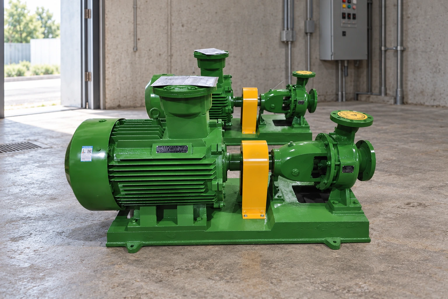
Choose a suction reference point and a discharge reference point. Account for elevation difference, required pressure difference, velocity-head difference when significant, and friction losses through suction and discharge pipes, fittings, valves, filters, heat exchangers, meters, and nozzles. In an open tank-to-open tank system, both surfaces may be at atmospheric pressure, but elevation and friction remain. In a closed or pressurized system, required destination pressure can dominate. Document the equation and the basis for each term so another reviewer can reproduce it.
Understand static and friction components
Static head depends mainly on the elevation and pressure boundary and does not vanish when flow is zero. Friction head rises with flow and depends on inside diameter, length, roughness, viscosity, fittings, and equipment. This creates a system curve. The pump operating point is where that system curve intersects the pump curve at the current speed and impeller. A throttled valve increases resistance and shifts the point; it does not make the pump independently deliver its published maximum flow and maximum head at the same time.
Таблица решений
| Конструкция головки | What it represents | Typical input |
|---|---|---|
| Elevation head | Vertical energy difference | Source and destination elevations |
| Pressure head | Required pressure difference | Vessel or terminal pressures and density |
| Velocity head | Difference in flow velocity energy | Pipe areas and velocity |
| Friction head | Losses while liquid flows | Pipe, fittings, valves and equipment |
Use the correct suction level
For a well, tank, pit, or reservoir, use the operating liquid level for the case being checked. The lowest source level often gives the highest static lift. In a pressurized suction vessel, include that pressure correctly. Suction gauge readings near the pump can support diagnosis but do not replace the full energy balance. Net positive suction head is a related but separate check comparing the absolute suction energy above vapor pressure with the pump's requirement and the project margin. Confusing discharge head with NPSH can lead to cavitation.
Plot more than one duty point
Calculate normal, minimum-flow, maximum-flow, lowest source level, highest destination pressure, dirty-filter, alternate pipe route, and parallel-pump cases that can actually occur. Plot them on the certified curve. Check efficiency, absorbed power, motor load, minimum continuous flow, runout, shutoff, vibration, and any preferred operating region. For variable speed, review the full speed and control range rather than one nominal point. A single total dynamic head value can hide an operating envelope that the selected pump cannot safely cover.
Verify head in the field
At commissioning, measure suction and discharge pressure at known elevations, flow, speed, liquid condition, source and destination levels, and valve positions. Correct gauge readings to consistent reference points and include velocity effects if material. Compare the calculated differential head with the curve and motor input. Calibration, trapped air, pulsation, blocked gauge lines, and poor tap locations can distort results. Preserve the field readings and system configuration so later performance tests use the same basis.
Выбор системы, подтверждающие материалы и закупочная документация
Оцените насос как часть гидравлической системы, а не как изолированный двигатель и крыльчатку. Определите жидкость, температуру, содержание газа и твердых частиц, уровень источника, требуемый диапазон расхода, уровень или давление нагнетания, размеры всасывающей и нагнетательной труб, арматуру, клапаны, фильтры, высоту расположения, часы работы, пуски, метод управления, электропитание, условия окружающей среды и требование к резервированию. Рассчитайте нормальный и предельный общий динамический напор, затем постройте графики для этих случаев по сертифицированной характеристике. Проверьте потребляемую мощность, КПД, пределы минимального расхода или охлаждения, условия всасывания, совместимость материалов и последствия блокировки или перекрытия тракта.
Используйте измерения для разделения гидравлических, механических, электрических и технологических причин. Систематическая запись может включать расход, давление на входе и выходе, уровень в источнике и приемнике, напряжение, ток, мощность, частоту вращения, вибрацию, температуру подшипников, утечки, шум, время работы, количество пусков, положение клапана и состояние жидкости. Сравнивайте аналогичные показания при стабильном режиме работы. Единственный симптом редко доказывает, какой именно компонент вышел из строя, а замена деталей без определения рабочей точки может скрыть реальную проблему системы.
Для закупки и приемки определить границы поставки, точки ответственности, материалы, соединения, габариты, привод, контроллер, защиту, приборы, опорную раму, ограждения, подъемные приспособления, покрытие, испытания, документацию, ЗИП, консервацию, монтаж и пусконаладку. Устранить отклонения до заключения договора. Во время пуска проверить направление вращения (где применимо), положение запорной арматуры, смазку, центровку, уставки защиты, отсутствие утечек, уровень шума и вибрации, расход, давление, ток и срабатывание сигнализации по утвержденным процедурам. Сохранить опросный лист, характеристику, чертежи, уставки, руководства, протоколы испытаний и исходные данные (базовые замеры) для последующего технического обслуживания.
A pillar guide should also be used as a shared calculation and review reference. Define the measurement points, coordinate system, units, liquid properties, normal and limiting cases, instrument accuracy, acceptance tolerance, and responsible reviewer. Keep the calculation assumptions beside the selected curve and revise them when pipe routes, levels, valves, equipment, controls, or operating objectives change. During technical bid review, normalize every supplier offer to the same duty and boundary before comparing efficiency, motor size, price, or delivery. During commissioning, measure the same variables used in the calculation and reconcile any difference before accepting the system. During operation, trend those readings at a repeatable condition so wear, blockage, changed resistance, incorrect valve position, sensor drift, or source variation can be separated. This creates one dependable chain from design through procurement, startup, and maintenance instead of several disconnected estimates. Include the approved drawings, calculation, curve, data sheet, deviations, test records, settings, spare-parts list, and operating limits in the final handover package. A future change should be checked against this baseline rather than judged from a single pressure gauge or subjective observation.
Use consistent terminology across the hydraulic calculation, equipment schedule, control narrative, piping drawing, instrument list, and commissioning procedure. State whether each pressure is gauge or absolute, whether each elevation refers to pipe centerline or liquid surface, which inside diameter was used for friction, and what fluid density, viscosity, temperature, and vapor pressure apply. Mark temporary hoses, bypasses, partially open valves, dirty filters, and future connections because they change the system curve. Where several pumps operate in parallel or series, calculate the combined curves and the credible combinations rather than multiplying one pump value. Review shutoff, runout, minimum flow, motor load, suction margin, transient pressure, and failure response. Field instruments should have suitable range, accuracy, location, and calibration evidence. If measured performance differs from the prediction, first verify the test configuration and instruments, then reconcile the pump curve and system curve. Do not change an impeller, speed, valve, setpoint, or motor until the responsible review confirms the effects across every operating case.
When teaching or reviewing head, work through one clearly labeled example without turning it into a universal answer. Sketch the source and destination, select datum elevations, mark liquid levels and pressure boundaries, list each pipe segment and fitting, and show the assumed flow. Calculate the static contribution first, then the friction contribution at several flows, and plot the system curve. Add the pump curve for the actual speed and impeller and identify the intersection. Next change one variable at a time—source level, valve resistance, filter condition, destination pressure, parallel operation, or speed—to show why the operating point moves. Finally check power and suction margin and state what cannot be concluded from discharge pressure alone. This method helps readers detect sign errors, mixed units, omitted pressure terms, use of outside rather than inside pipe diameter, and the common mistake of adding a pump's maximum flow to its maximum head. Keep the worked sheet with the project so the result can be updated instead of recreated from memory.
Как эта тема связана с оборудованием BORRAPUMP
Это руководство способствует раннему рассмотрению what is head in a pump приложений. Она не назначает окончательную модель. Отправьте данные о жидкости, диапазоне расхода, общем напоре, уровнях источника и назначения, содержании твердых частиц, рабочем цикле, мощности, средствах управления, условиях на объекте, количестве, пункте назначения и требуемых согласованиях, чтобы оборудование можно было проверить на соответствие реальным условиям эксплуатации.
Связанные технические руководства BORRAPUMP
Авторитетные источники и дальнейшее изучение
Насосные системы Министерства энергетики США; Hydraulic Institute pump resources; NIST SI units. Эти источники содержат общие инженерные, водные, экологические или защитные сведения; действующие местные правила, утвержденные проекты и инструкции к оборудованию остаются приоритетными.
Познавательное видео от Practical Engineering: Создают ли насосы давление или поток?.
Apply the calculated head to the actual pump
After calculating total dynamic head, read the matching centrifugal pump curve and find the intersection with the system curve. Keep the separate NPSH available and required check with that selection; discharge head alone does not establish an acceptable suction margin.
Часто задаваемые вопросы
Is pump head the same as pressure?
No. They are related through liquid density and gravity, but head is energy per unit weight.
Does maximum head occur at maximum flow?
No. On a typical centrifugal pump curve, shutoff or maximum head occurs near zero flow.
What is total dynamic head?
It is the required energy difference including elevation, pressure, velocity, and friction terms between defined points.
Is suction lift included in pump head?
Yes, the source condition is part of the system energy balance, while NPSH remains a separate cavitation check.
Последняя контрольная точка
Перед изменением оборудования или параметров согласуйте фактический режим работы и условия на объекте с утвержденной характеристикой, чертежами, материалами, электропитанием, средствами управления, защитой, монтажом, испытаниями и доступом для технического обслуживания. Зафиксируйте оставшиеся допущения и назначьте ответственных за их закрытие. Сохраните конечные показания и документы в качестве исходных данных для будущих проверок.
Полезная передача дел также указывает, что не было протестировано, какие предположения по-прежнему зависят от подтверждения на объекте и когда назначена следующая проверка. Определите лицо, ответственное за учет уровня воды, давления, расхода, электрических параметров, сигналов тревоги и технического обслуживания. Храните фотографии и сведения об инструментах вместе с результатами. Если последующее снятие показаний выполняется при другом положении клапана, уровне источника, скорости, настройке давления или водоразборе, отметьте это различие перед сравнением тенденций. Эта простая дисциплина предотвращает ошибку, при которой нормальное изменение режима работы принимается за повреждение, и не позволяет списать реальное ухудшение состояния на обычные колебания. Если на карту поставлены безопасность, санитария, водоснабжение или ущерб имуществу, определите временную защиту и порядок эскалации до возвращения системы в режим работы без присмотра.
Используйте первую проверенную рабочую запись в качестве базовой линии, а затем сравнивайте будущие проверки в максимально близких практических условиях. Фиксируйте погоду, уровень жидкости, нагрузку, положение клапанов, скорость, состояние фильтра и наличие любых временных шлангов или байпасов. Убедитесь, что манометры и измерительные приборы имеют подходящий диапазон и что показания снимаются в одних и тех же точках. Изменение одного показателя должно вызывать необходимость анализа связанных данных, а не немедленную замену деталей. Если насос, электродвигатель, система управления, резервуар, клапан, трубопровод или источник заменяются, обновите чертеж и учетную карту выбора оборудования. Это позволяет принимать решения по техническому обслуживанию на основе реальной системы и дает поставщикам достаточно контекста для оценки гарантийного случая, замены или регулировки режима работы без необходимости начинать расследование с нуля.