
Centrifugal pump minimum flow is the lower operating limit specified for the actual pump and service conditions. It matters because a pump can remain running while operating in a condition that creates excessive heating, unstable hydraulic behavior or damaging mechanical loads. Minimum thermal flow and minimum continuous stable flow address different concerns and should not be assumed identical. Obtain the limits for the supplied configuration, then check every operating case against them. A bypass, a control strategy or a smaller pump must be evaluated as part of the system; no universal percentage of best-efficiency flow is established by this guide.
Ask which minimum-flow limit is being quoted
A specification that says only minimum flow can conceal an important distinction. A thermal limit addresses the temperature behavior of the liquid and equipment at low flow. A stability-related limit addresses acceptable continuous hydraulic and mechanical operation. The applicable lower limit can depend on the design, speed, liquid and service condition. Ask the supplier to identify the term, the basis and the conditions attached to the value.
Request the permitted continuous operating range and any restrictions on short-duration operation. An allowance for a controlled startup event is not necessarily permission for sustained low-demand service. Record the limits with the pump curve and operating instructions so that an operator does not have to infer them from a single design-point marker.
Separate system demand from flow through the pump
The amount of water required by the downstream process is not always the same as the flow passing through the pump. If an approved recirculation arrangement returns some liquid, pump flow includes that returning stream. A process flowmeter located after the return branch can therefore show less than the total pump flow. The measurement location matters when deciding whether the pump is protected.
Draw the pump, branch, return destination and flowmeter positions. Identify which measurement the control system uses and what happens if that signal fails. A bypass line on a drawing does not prove that enough liquid will pass through it in every case. Its valve position, resistance, available pressure and receiving condition determine the flow it can provide.
Review the entire duty range
Include normal demand, low demand, startup, shutdown, standby changeover and unusual valve positions. For parallel pumps, check the cases in which one unit runs and several units run. A unit selected for a high combined demand may operate quite differently when a single downstream user remains. Avoid evaluating the arrangement only at the maximum duty.
Use the centrifugal pump curve guide et le duty point calculation guide to establish the operating point for each case. Confirm the actual speed and impeller configuration. If demand is too low for the permitted range, the review should identify how the control or equipment selection will change rather than marking the design-point calculation complete.
Understand why low flow can be harmful
A centrifugal pump transfers energy to the liquid. At very low throughflow, the operating condition can produce heating and unfavorable internal hydraulic behavior. The resulting concerns depend on the pump design and service. Do not diagnose a particular failure merely because low flow is possible, but do not assume that a motor drawing current proves healthy pumping.
Le DOE pumping-system sourcebook discusses the relationship between selection, control and efficient system operation. Use that relationship when evaluating a low-demand condition. The pump’s allowable range and the installation’s safe operating limits remain the source of acceptance criteria; a general explanation cannot establish a minimum flow for every pump.
Use a decision table for low-demand operation
| Observed condition | Question to resolve | Possible design response to evaluate |
|---|---|---|
| Demand frequently below the permitted range | Was the pump selected for the real demand profile? | Smaller duty unit or staged equipment |
| Low flow occurs during startup | What duration and sequence are permitted? | Approved start sequence and protection |
| Recirculation exists but flow is unknown | Does the branch provide enough flow in every case? | Calculation, measurement and suitable control |
| Return liquid becomes warmer | Is heat accumulating in the return destination? | Review return location and thermal balance |
| Variable speed is proposed | What range is permitted at the proposed speeds? | Revised operating envelope and control review |
These are review questions, not automatic approvals of a bypass, speed reduction or other modification. Use the supplied pump limits and engineering assessment to choose the response.
Evaluate recirculation as an engineered arrangement
A return branch can maintain flow through the pump when useful downstream demand is lower. The design must establish the required branch flow under the relevant conditions, the receiving location and the behavior of any regulating device. Check the pressure rating and the consequences of a closed, blocked or failed branch. The bypass must remain part of the operating and maintenance records.
Consider where the return liquid goes. Returning a small stream to a large reservoir differs from repeatedly circulating liquid through a small volume near the suction connection. Heat can accumulate in a restricted loop. The designer should review the thermal behavior and suction conditions rather than assuming that any visible return line provides adequate protection.
Check control options against the pump limits
Speed control can change the operating point, but it does not eliminate every minimum-flow issue. Obtain the permitted operating range at the proposed speeds and review the motor and drive requirements. Low-demand operation may still fall outside an acceptable range. The control system needs suitable limits and a defined response when demand or instrumentation becomes abnormal.
Staging a smaller pump or stopping a unit can be appropriate in some systems, but each proposal needs a review of pressure, storage, start frequency and response time. Do not trade a continuous low-flow problem for excessive cycling or inadequate service. Choose the arrangement from the actual demand profile and the requirements of the downstream users.
Confirm measurements at the correct locations
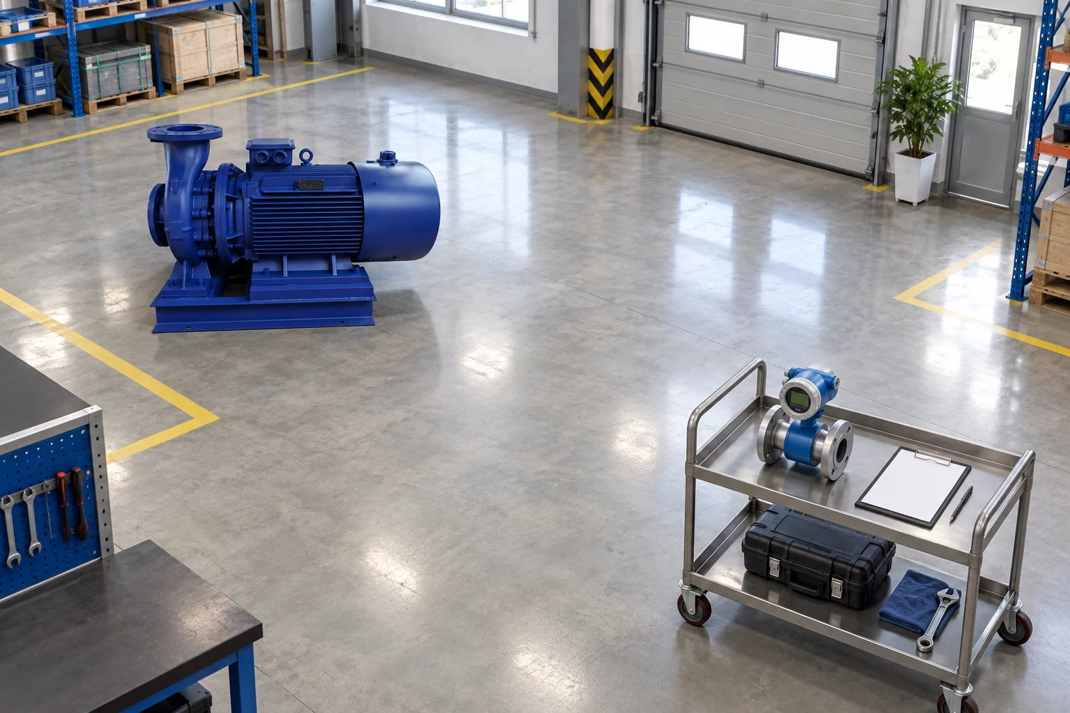
Record how flow is measured and whether the measurement includes the return branch. Check the instrument range and suitability for the low-flow case. A meter selected only for maximum capacity may not give useful evidence near the lower operating limit. State how an operator recognizes loss of the required flow and how the control system responds.
Keep pressures, speed, liquid temperature, valve positions and system configuration with the flow readings. A commissioning record that gives only one flow figure can be difficult to interpret later. When the route or valve arrangement changes, establish a new comparable operating record. Do not compare an altered system against the original result without recording the difference.
Keep suction conditions in the review
Low-flow protection and suction adequacy address different questions. A return arrangement can affect the condition of the liquid reaching the pump, particularly if temperature increases or air is introduced. Review the source level, suction losses and liquid temperature for the proposed arrangement. See the related NPSH selection guide for the distinction between available conditions and the pump’s requirement.
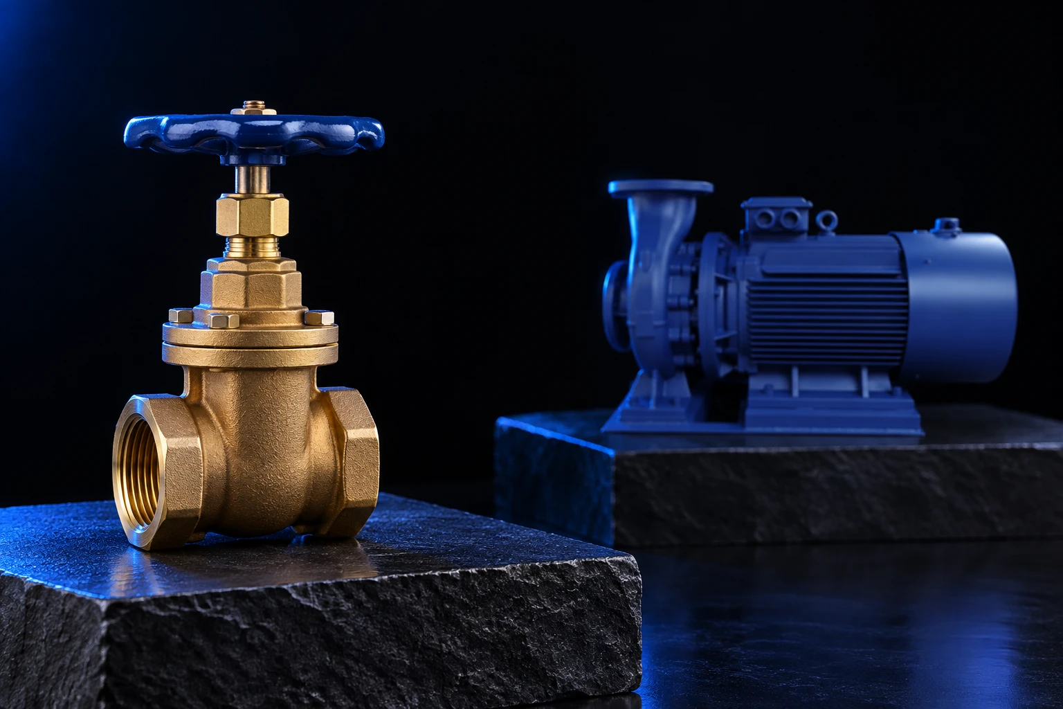
For the BorraPumps ISW horizontal inline pump, request limits for the actual supplied configuration and service. Do not assume a minimum-flow value from a similarly sized unit or infer it from the product image. The correct quotation should define the duty range and the required protection or control provisions.
Investigate operation outside the approved range
If the pump is suspected of sustained low-flow operation, first establish the actual configuration and measurements. Review closed valves, obstructed routes, control settings, return-branch condition and downstream demand. Abnormal heat, vibration or sound should prompt the approved response, but these observations alone do not identify a single cause.
Use the manufacturer’s troubleshooting procedure and the site’s safety rules. The HSE isolation guidance explains the need to prevent reenergization during electrical work. The complete maintenance procedure must also address pressure and mechanical energy. Do not adjust or inspect rotating components while treating an electrical stop command as sufficient isolation.
Write minimum-flow requirements into procurement
Provide the expected maximum, normal and minimum demands, the liquid conditions, source and destination levels, operating schedule and proposed controls. Ask for the continuous operating range, the defined minimum-flow limits, any temporary operating allowances and the required monitoring. Request the basis for a proposed return arrangement and its inclusion in the acceptance procedure.
During commissioning, verify the agreed low-demand case without deliberately exceeding the equipment’s permitted limits. Record which protection functions and alarm responses were checked. Keep the approved configuration with the asset record, including any bypass settings, meter locations and control revisions. Future modifications can then be reviewed against a known operating envelope.
Learning resource
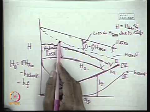
NPTEL’s lecture on centrifugal pump characteristics supports understanding the operating curve and the relationship between flow and head. It does not supply model-specific minimum-flow limits.
Foire aux questions
Is minimum flow always a fixed percentage of best-efficiency flow?
No universal percentage is established here. Obtain the limits and applicable conditions for the actual pump and configuration.
Does a bypass line automatically protect the pump?
No. Its flow, controls, receiving location and failure behavior must be verified for the relevant operating cases.
Does variable speed remove the minimum-flow requirement?
No. Review the permitted operating range at the proposed speeds and the actual low-demand condition.
Which flow measurement should be compared with the pump limit?
Use the flow through the pump as defined by the approved procedure. Check whether the meter includes or excludes a return branch.