
The pump duty point is the flow and head at which the selected pump and connected system operate together. Find it by intersecting the pump performance curve with the system curve at the same speed, liquid conditions and units. A requested flow-head pair is a design target; it becomes a verified installed duty only when the pump and system are shown to meet it. This guide explains the calculation and field checks for water-transfer systems using clearly identified illustrative values, not an invented Borra performance curve.
Separate requested duty from installed duty
A specification may request a certain flow at a stated head. That is the target used to select equipment. The installed system may operate elsewhere if the route, liquid levels or receiving pressure differ from the assumptions. Keeping these terms separate makes it easier to investigate whether a problem belongs to the pump selection or to the system calculation.
Record the operating cases before calculating. Include normal demand, low and high liquid levels, changed outlet conditions and permitted valve or speed settings. A duty point is not necessarily fixed throughout a cycle. For a transfer between tanks, falling source level and rising receiving level can move it even when no valve is adjusted.
Этот Borra IS clean-water centrifugal pump is a relevant equipment family for defined water-transfer duties. Obtain the offered model’s curve, speed and impeller data. Do not infer an operating point from a product photo or use a general catalogue range as a measured system result.

Build the system head requirement
A useful system-head calculation separates static requirements from flow-dependent losses. Static requirements include elevation difference and any pressure difference between source and destination, expressed consistently as head. Friction and fitting losses depend on the actual route and flow. The designer should select the loss method appropriate to the liquid and installation and document the inputs.
Record internal pipe bore, length, material, condition, fittings, valves, inlet and outlet arrangements. A nominal pipe size is not always the bore used in a loss calculation. For a replacement system, account for known deposits or changed routing. Do not conceal every uncertainty inside one large arbitrary allowance, because that makes later review and correction difficult.
For a simplified turbulent-flow illustration, write system head as Hs + KQ², where Hs is the static requirement and K represents the assumed route resistance with the chosen units. This is a simplified relationship, not a universal model for every liquid or flow regime. Use the actual hydraulic calculation for the project. The pump-head explanation helps keep head and pressure definitions consistent.
Obtain the correct pump curve
Confirm the exact model, impeller diameter, speed and liquid conditions. A curve for a different frequency or trim is not interchangeable with the proposed selection. Read any stated performance tolerances and operating limits. If the supplier offers a family chart, ask which line applies to the quotation and have the selected point identified.
Использовать how to read a centrifugal pump curve to interpret head, efficiency and power together. A numerical fit to the head curve can support a calculation only if it accurately represents the supplied data over the relevant range. Do not create a fictitious curve from a pump’s maximum head and maximum flow and present it as verified performance.
Этот DOE pump-system resources support matching equipment to the system. The result should be traceable to both the manufacturer’s data and the route calculation rather than a calculator output with hidden assumptions.
Find the intersection using a transparent example
Suppose an illustrative system has 10 m of static head and route losses represented by 0.004Q², with Q in cubic metres per hour. Its system curve is therefore H = 10 + 0.004Q². Suppose a purely hypothetical pump curve is H = 30 − 0.006Q² over the example range. These equations are invented only to demonstrate the mathematics; they do not describe any Borra pump.
Set the two expressions equal. Then 30 − 0.006Q² = 10 + 0.004Q², so 20 = 0.010Q². Q is approximately 44.7 cubic metres per hour. Substituting into either expression gives approximately 18 m of head. That pair is the intersection for these specific illustrative equations.
For a real selection, use the supplied curve and calculated system curve rather than these coefficients. Review the result against efficiency, power, suction conditions and permitted operation. A mathematical intersection outside the approved region is not an acceptable selection simply because the equations cross there.
Understand what moves the duty point
Increasing route resistance generally changes the intersection, often reducing flow for a fixed-speed centrifugal pump. Raising the required static head also changes it. Opening a valve, cleaning an obstructed line or lowering outlet pressure can increase delivered flow and alter motor loading. Check the actual shape of the selected curve rather than assuming a fixed response magnitude.
Liquid-level changes deserve explicit calculation. A low source level can increase static lift and reduce available suction head simultaneously. A high receiving level may impose an additional static requirement. Test combinations that can realistically occur together. Avoid combining impossible extreme assumptions while overlooking a common operating condition.
Suction performance must be reviewed at the resulting operating flow. See NPSH available versus required for that separate check. Total discharge head and suction margin are related through the installation but they are not interchangeable measures.
Document each case in a duty table
| Operating case | System inputs to change | Pump checks to repeat |
|---|---|---|
| Normal transfer | Normal source and receiving conditions | Flow, efficiency and power |
| Low source level | Increased static lift and changed suction level | Flow, submergence and NPSH |
| High receiving level | Greater outlet requirement | Delivered flow and loading |
| Higher pipe resistance | Changed friction or valve condition | Duty movement and permitted region |
| Reduced speed | Verified speed-specific performance | Flow, static-head capability and limits |
| Parallel operation | Common-main resistance and combined curve | Individual and combined performance |
This table records cases rather than universal performance trends or model ratings. Preserve the source of each input and identify what is measured, calculated or assumed. That distinction prevents a preliminary estimate becoming an apparently certified operating value in a purchase document.
Treat parallel operation as a new curve problem
When pumps operate in parallel, add their flows at a common head to obtain the combined pump curve. Then intersect it with the system curve for the common route. The combined installed flow is not generally twice the single-pump installed flow, because increased flow changes resistance in the common pipe. Include individual branch losses where they matter.
Check one-pump operation and any asymmetric configuration. A duplex system can meet peak flow with both units yet fail a required one-pump-out condition. Controls need to reflect the selected hydraulic cases rather than attempting to create capacity that the pumps and pipe cannot deliver. The duplex sewage control guide gives an example of coordinating those requirements.
Measure the installed operating point
During commissioning, use appropriate flow and pressure instruments and record speed, liquid levels and valve state. Convert readings to a consistent head basis with the correct reference positions, velocity terms and liquid density where required. A discharge-pressure reading alone is not always the total pump head, particularly where suction pressure or elevation differences are significant.
If a flowmeter is unavailable, use only an approved alternative method appropriate to the installation and its limitations. A tank-volume test needs a valid volume relationship and allowance for simultaneous inflow. Do not estimate flow directly from motor current without a justified calibrated method. Record uncertainty so the measured point is not portrayed as exact beyond the instrument’s capability.
The initial result becomes a baseline. If later duty changes, compare the route, liquid conditions, instrumentation and pump condition before selecting a replacement. An apparent loss of capacity may result from increased system resistance rather than an undersized original pump.
Prepare the selection package
Include the design target, important operating cases, system calculation, route drawing, liquid information and the manufacturer’s selected curve. Ask the supplier to identify allowable operation, power demand and suction requirements at each case. The Hydraulic Institute operating-region guidance provides useful context for the limits that must accompany a selected intersection.
Keep preliminary and final versions distinct. Record revised pipe routes, changed receiving pressure and measured commissioning results in the same duty record. This preserves the connection between the original selection and what the station actually does, making later troubleshooting and energy review more reliable.
For the wider water-transfer selection, use the end-suction pump guide alongside this specific calculation or construction review.
Часто задаваемые вопросы
Is duty point the same as rated flow?
Not necessarily. A rated flow is stated under specified conditions. The installed duty point depends on the pump curve and connected system. Confirm both flow and head, together with the exact operating configuration.
Can I find duty from shutoff head alone?
No. Shutoff head is a zero-flow condition. You need the pump performance over flow and the system-head requirement to determine the installed intersection.
Does closing a valve leave motor loading unchanged?
Do not assume that. It changes system resistance and duty, and power response depends on the selected pump curve. Review the actual loading and permitted region for the new condition.
What makes an intersection unacceptable?
It may miss required flow, overload equipment, provide inadequate suction margin or fall outside permitted operation. A valid numerical intersection still needs a complete engineering selection check.
Повышение квалификации
This NPTEL educational lecture explains centrifugal pump characteristics used in the hydraulic selection above. It does not verify a Borra rating or replace the selected model curve.
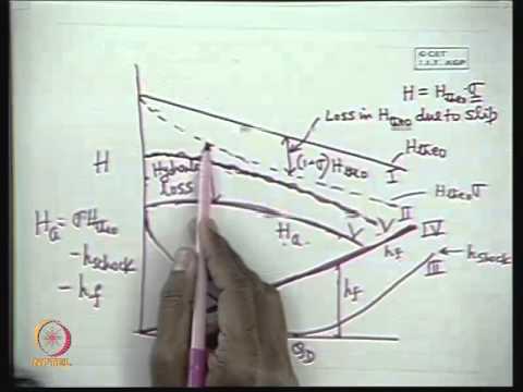
Watch nptelhrd: Mod-01 Lec-15 Characteristics of a Centrifugal Pump