
A well pump control box is an above-ground enclosure used with many three-wire single-phase submersible motors. It commonly contains the starting components and connection points that help the motor start and run, while the pressure switch or another controller tells the system when water is needed. Not every well pump uses a separate box: many two-wire submersible motors contain their starting components internally, and larger or three-phase systems use different starters and protection. The box must match the motor manufacturer's model, voltage, phase, horsepower, wiring, and protection requirements.
This article is a practical diagnostic and procurement guide, not a substitute for the pump manufacturer's instructions, an approved system design, current electrical and plumbing rules, or qualified site service. Isolate energy and pressure before opening equipment. Well work, lifting, confined spaces, wastewater, wet electrical locations, and energized testing require competent personnel and task-specific controls.
Understand what the box does
In a typical compatible three-wire arrangement, the box houses a start capacitor, run capacitor where the design uses one, relay, terminals, and sometimes overload or additional protection. The precise circuit varies. It does not create water pressure by itself; it supports motor starting and operation after a pressure switch, level control, variable-speed controller, or other device calls for the pump. Treat the lid diagram and manufacturer instructions as controlling. A box with the same nominal horsepower but the wrong motor family or component values can cause unreliable starting or motor damage.
Distinguish two-wire, three-wire, and larger systems

Wire-count labels usually refer to motor leads and often exclude the equipment grounding conductor, so casual counting at a cable can mislead. A two-wire single-phase submersible motor typically has its starting arrangement inside the motor. A three-wire single-phase motor commonly relies on an external control box. Three-phase motors use contactors, overloads, phase protection, and controls appropriate to the installation rather than the same small residential box. Variable-frequency drives add their own motor, cable, grounding, cooling, and programming requirements. Identify the exact motor and diagram before purchasing or touching controls.
Recognize symptoms without jumping to a conclusion
No water, humming, rapid clicking, failure to start, nuisance trips, burnt odor, swollen capacitor, loose or discolored terminals, or intermittent operation can involve the control box. Similar symptoms can come from supply voltage, pressure switch, wiring, cable, motor, locked pump, dry well, pressure tank, or pipework. Do not replace capacitors by appearance alone or repeatedly reset an overload. Record when the fault occurs and whether pressure, voltage, current, or controller indication changes. Qualified testing should isolate the circuit and use the manufacturer's resistance and component procedures.
Таблица решений
| System clue | Common arrangement | What must be verified |
|---|---|---|
| Two-wire single-phase motor | Starting components often inside motor | Exact motor design and diagram |
| Three-wire single-phase motor | External control box often required | Approved motor/box match |
| Three-phase motor | Starter and phase/overload protection | Voltage, phase, settings and sequence |
| Variable-speed system | Drive-based control | Motor, cable, grounding and programming |
Match a replacement correctly

Use the motor model, voltage, phase, horsepower, service factor or specified load, and the manufacturer's approved control-box reference. Confirm enclosure environment, cable distance and conductor sizing, grounding, disconnecting means, short-circuit and overload protection, pressure-switch rating, and compatibility with generators or drives. Do not substitute a generic box because the terminals look similar. Where lightning, voltage variation, dry running, phase issues, or low water are credible, review appropriate protection with the responsible designer instead of adding uncoordinated devices.
Install in a suitable location
The enclosure needs the environmental rating, mounting orientation, ventilation, clearances, and accessibility specified by its manufacturer and applicable rules. Protect it from flooding, condensation, corrosive atmosphere, direct weather, pests, impact, and unauthorized access. Cable entries should preserve the enclosure rating and strain relief. Keep the wiring diagram and identification legible. Wet hands, standing water, and open energized panels are a dangerous combination. Installation, component testing, and energized measurements belong to qualified electrical personnel using site procedures and suitable protective equipment.
Commission and maintain the complete control chain
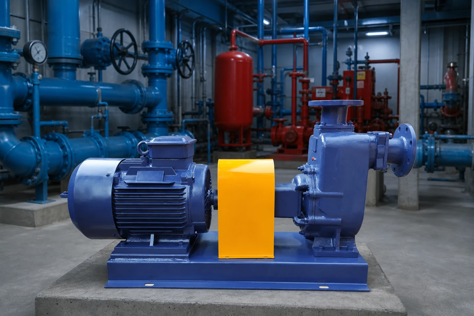
Verify the supply, disconnect, grounding, pressure or level signal, control-box connections, motor cable, protection settings, and direction of rotation where applicable. Record line voltage, starting behavior, running current, pressure settings, starts, runtime, and pump response. Listen for repeated relay chatter and inspect for heat or loose connections only under safe isolated conditions. Maintenance intervals depend on the enclosure, environment, duty, and manufacturer. Keep replacement component values and the motor-control match in the site record; a future box should not be selected from memory.
System selection, evidence, and procurement record
A well-pump decision should begin with the well record rather than the nameplate on the failed unit. Record drilled depth, casing diameter, static water level, pumping water level at a stated test flow, recovery, water quality, pump setting, rising-main size, pressure setting, storage volume, supply voltage, and the present control sequence. The pumping level—not the bottom of the well—is the starting point for the lift calculation. Add discharge pressure and pipe losses to establish total dynamic head, then compare the expected operating range with a current certified curve. The sustainable yield of the well can be lower than the short-term demand of the building. Storage and controls may therefore be more important than selecting a larger pump.
Treat electrical and hydraulic evidence as one record. Pressure, flow, water level, voltage, running current, starting behavior, insulation condition, runtime, starts, and controller events help separate a pump fault from a dry or declining well, leaking pipe, failed check valve, waterlogged pressure tank, obstructed line, low voltage, or incorrect control setting. Measurements must be made with suitable instruments by people qualified for the work. Never open energized equipment, pull a submersible pump, or enter a well enclosure without the required isolation, lifting plan, sanitation controls, and site procedure.
For procurement, ask every supplier to quote the same boundary: pump and motor, cable, splice, rising main, check valves, wellhead fittings, pressure tank, sensors, controller, protection, installation, lifting, testing, documentation, commissioning, and disposal of removed equipment. Compare the complete installed scope rather than the pump price alone. Require dimensional data, materials, curve, absorbed power, motor data, minimum submergence, cooling requirements, permitted starts, controls, installation instructions, test records, spares, and warranty conditions. At commissioning, preserve baseline readings so future diagnosis can distinguish normal aging from a changed well or system.
Как эта тема связана с оборудованием BORRAPUMP
This guide supports early review of what is a well pump control box applications. It does not assign a final model. Send the liquid, flow range, total head, source and destination levels, solids, duty cycle, power, controls, site conditions, quantity, destination, and required approvals so equipment can be checked against the real service.
Связанные технические руководства BORRAPUMP
Авторитетные источники и дальнейшее изучение
OSHA electrical safety; OSHA control of hazardous energy; U.S. Department of Energy motor systems. These sources provide general engineering, water, environmental, or safety context; current local rules, approved designs, and equipment instructions remain controlling.
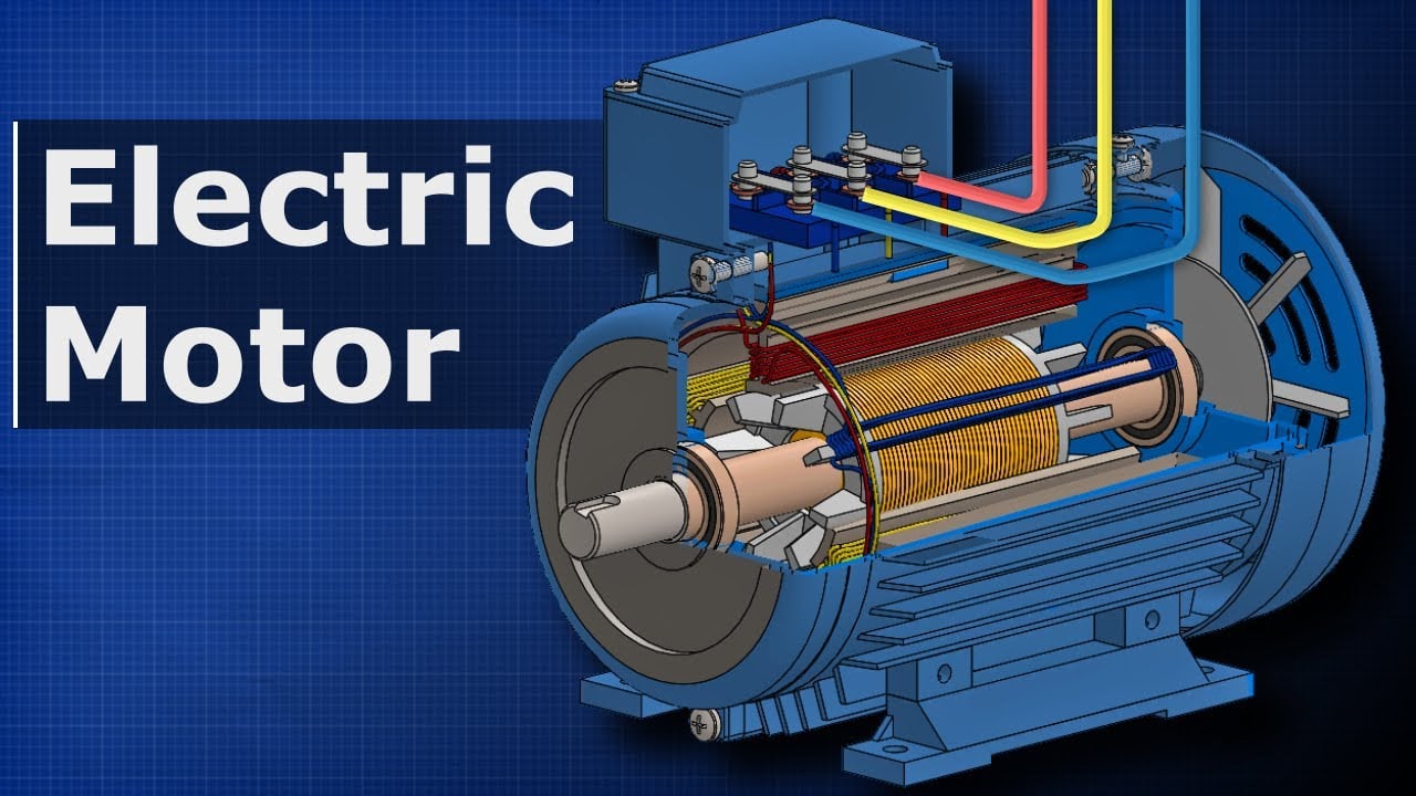
Educational video by The Engineering Mindset: How Electric Motors Work: Three-Phase AC Induction Motors.
Часто задаваемые вопросы
Does every well pump need a control box?
No. Many two-wire motors have internal starting components, while compatible three-wire motors commonly use an external box.
Can I use any box with the same horsepower?
No. It must match the exact motor family, voltage, phase, horsepower, wiring, and manufacturer requirements.
Is the pressure switch inside the control box?
Sometimes controls are combined, but many systems use a separate pressure switch. Follow the actual diagram.
Can I test a control box myself?
Opening and energized testing expose dangerous voltage. Use qualified electrical personnel and manufacturer procedures.
Final checkpoint
Before changing equipment or settings, reconcile the actual duty and site conditions with the approved curve, drawings, materials, power, controls, protection, installation, testing, and maintenance access. Record remaining assumptions and assign responsibility for closing them. Preserve the final readings and documents as the baseline for future inspection.
A useful handover also states what was not tested, which assumptions still depend on site confirmation, and when the next inspection is due. Identify the person responsible for water-level, pressure, flow, electrical, alarm, and maintenance records. Keep photographs and instrument details with the results. If a later reading is taken at a different valve position, source level, speed, pressure setting, or demand, label that difference before comparing trends. This simple discipline prevents a normal operating change from being mistaken for damage and prevents real deterioration from being dismissed as normal variation. When safety, sanitation, water supply, or property damage is at stake, define the temporary protection and escalation route before returning the system to unattended service.
Use the first verified operating record as a baseline, then compare future checks under the closest practical conditions. Note weather, liquid level, demand, valve positions, speed, filter condition, and any temporary hose or bypass. Confirm that gauges and meters have an appropriate range and that readings are taken from the same locations. A change in one number should trigger a review of connected evidence rather than an immediate part replacement. If the pump, motor, control, tank, valve, pipe, or source is changed, update the drawing and selection record. This keeps maintenance decisions tied to the real system and gives suppliers enough context to evaluate a warranty question, replacement, or operating adjustment without starting the investigation from zero.