
Booster pump pressure transducer calibration should establish whether a known pressure produces the correct sensor output and the correct controller indication. Compare the instrument with a suitable pressure reference, verify its configured range and units, and record the condition before making adjustments. A matching reading at one operating pressure does not prove that the full measurement chain is correct. This guide focuses on the electronic signal and controller display, rather than pressure-sensor location or mechanical gauge calibration. The test method, permitted errors and safe operating arrangement must come from the installed equipment documents and the project commissioning plan.
An inaccurate signal can make a healthy pump appear unable to reach pressure, or cause the controller to maintain the wrong actual pressure. However, changing calibration to make a pump meet an unrealistic setpoint conceals the real problem. First decide whether the investigation concerns measurement, hydraulic capacity, or control response.
Define the measurement chain before touching the settings
Write down the sensor tag, serial number, pressure range, output type and pressure reference. Gauge pressure, absolute pressure and differential pressure are different quantities. A gauge-pressure sensor can use atmosphere as its zero reference under the correct conditions; that does not make atmospheric exposure an appropriate zero test for every sensor type.
Trace the signal from the pressure connection through the transducer, cable, input module and controller to the displayed engineering units. Identify any separate value sent to a building management system. A correct local display does not automatically validate a second network value that has its own scale or unit conversion.
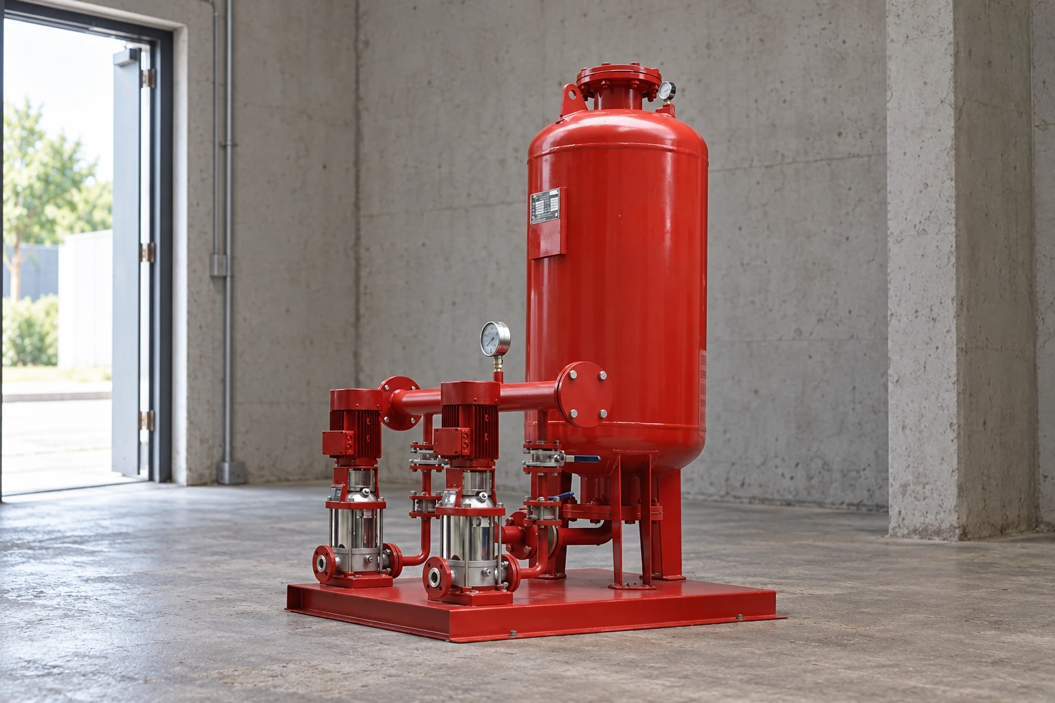
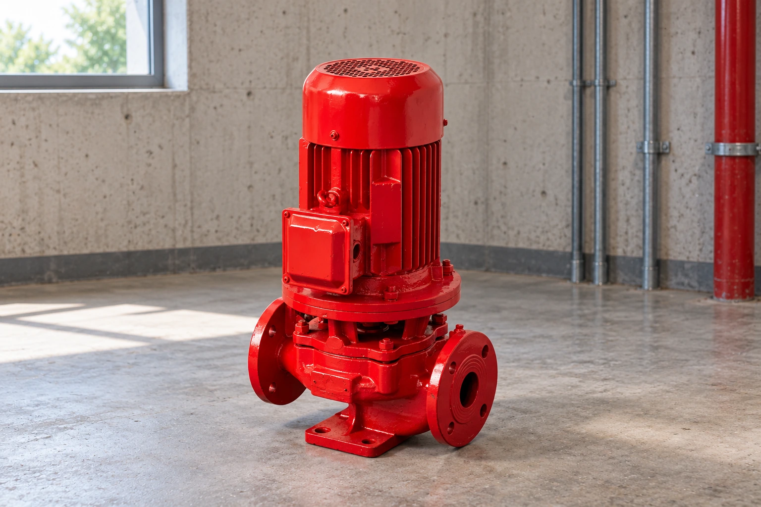
For a Borra booster-regulator water supply package, request the supplied controller and instrument documents before defining a calibration procedure. Product photographs illustrate equipment families; they do not establish which transmitter range, terminal arrangement or software version is fitted to a particular order.
Separate a calibration check from an adjustment
A calibration check compares indicated values with reference values under stated conditions. An adjustment changes the instrument or its configuration. Keep these activities separate in the record so that the original error remains visible. Otherwise, a technician may return a system to service without knowing how far the previous readings were wrong.
Choose a reference whose range, uncertainty and media compatibility suit the decision. Display resolution alone is not enough. A reference with many decimal places may still be unsuitable if its uncertainty is large compared with the project’s permitted measurement error. Include the reference identification and calibration status in the worksheet.
NIST’s explanation of metrological traceability is useful when reviewing the reference certificate: traceability concerns a measurement result and its documented calibration chain, including uncertainty. A label saying “traceable” does not by itself establish that a particular field measurement is fit for its intended purpose.
Make the pressure and electrical work safe
The test plan should identify how water service will be maintained while the sensor is unavailable. A controller receiving an artificial signal may change pump speed or staging. Use the manufacturer’s approved maintenance mode and the site’s control arrangements; do not inject signals into an active automatic loop without controlling the consequences.
Depressurize and verify the pressure boundary before disconnecting an instrument. Stored pressure can remain behind valves, and a controller stop command is not electrical isolation. Electrical testing belongs with qualified personnel using the specified equipment and isolation method. Avoid opening connections merely to see whether water comes out.
Use compatible clean fittings and a controlled pressure source. Protect potable-water cleanliness where applicable. Support the instrument and tubing so that the test connection does not impose bending loads on the sensor body. Check component pressure limits throughout the temporary setup, including hoses, adaptors and the reference instrument.
Check configuration before assuming the sensor has drifted
Compare the sensor nameplate range with the input configuration. A replacement transmitter may physically fit while using a different pressure range or output. Confirm the selected input type, engineering-unit endpoints, signal polarity where relevant, and any configured filtering. Record settings before changing them.
Use the existing pressure-sensor placement guide to understand what location the signal represents. Two instruments at different elevations or on opposite sides of a restriction may legitimately disagree. Calibration cannot remove a real hydraulic pressure difference between their measuring points.
Inspect connections for obvious damage and review recent work. A new sensor, controller replacement or software restoration is a useful trigger for checking the entire chain. An unexplained discrepancy that appears only when a motor operates may require investigation of wiring, grounding or signal integrity rather than a zero adjustment.
Use pressure comparison and electrical simulation for different questions
A controlled pressure comparison tests the sensor response together with the connected indication, depending on the setup. An electrical signal simulation at the controller input checks the downstream input and scaling while excluding the pressure-sensing element. Document the injection point; otherwise, the report can imply that a sensor was tested when it was bypassed.
For a transmitter explicitly documented as linear 4–20 mA, the expected pressure is:
Pressure = lower range value + ((current − 4 mA) / 16 mA) × pressure span.
As an illustrative calculation only, a 0–10 bar transmitter producing 12 mA represents 5 bar. If the controller is instead configured for 0–16 bar, that same current displays 8 bar. This is a scaling mismatch, not evidence that the water pressure has changed. The values are examples, not Borra product specifications or recommended pressure settings.
This equation does not apply unchanged to voltage-output sensors, digital instruments, nonlinear devices or signals with different endpoints. Consult the installed instrument manual. Signal loss and out-of-range behavior also need their own functional checks; a value below the normal measurement band should not automatically be treated as an ordinary pressure reading.
Record multiple points and the direction of approach
Select test points that cover the operating and protective decision ranges without exceeding any equipment limit. At each point, allow the reference and indication to settle under the approved procedure. Record the applied pressure, sensor output where measured, controller display and any separate supervisory display at the same time.
Where the procedure calls for increasing and decreasing pressure, preserve both sets of readings. Different results at the same reference pressure can reveal hysteresis or instability that a single ascending pass misses. Record environmental and installation conditions that could influence the comparison, rather than reporting an unexplained average.
The EPA technical reference on monitoring instruments discusses pressure-transducer characteristics and calibration concepts. It is background on measurement, not a booster-pump acceptance standard. Use the actual transmitter instructions and project criteria for test points, conditioning, adjustments and acceptance limits.
| Quan sát | Useful next comparison | What the finding does not prove |
|---|---|---|
| Similar offset across several pressures | Check zero reference and documented adjustment history | That the pressure connection is clear during operation |
| Error increases with pressure | Compare transmitter range, output and input scaling | That changing the pump setpoint will correct the error |
| Sensor output agrees but controller display does not | Check input type, units and configured endpoints | That the pressure element needs replacement |
| Local display agrees but supervisory display differs | Compare communication mapping and remote scaling | That the local control loop is inaccurate |
| Readings settle slowly or behave inconsistently | Investigate pressure path, filtering and signal stability | That every slow response is a calibration fault |
This is a diagnostic comparison table, not an acceptance table. Establish permitted errors before testing and express them consistently, such as pressure units or the specified percentage basis. Do not mix percentage of reading with percentage of full span.
Restore the real signal and witness operation
After any approved adjustment or replacement, repeat the required measurement checks and preserve the final results alongside the original readings. Reconnect the real sensor, remove temporary signal sources and restore documented configuration. Verify that no maintenance override or forced value remains active.
Then perform a controlled operational check. Observe actual pressure, displayed pressure, pump response and relevant alarm behavior through representative demand conditions. Keep protective functions active or manage their temporary unavailability through the approved test plan. A good bench result does not prove that a blocked installed connection responds correctly.
Sử dụng booster commissioning checklist for the broader handover, and investigate recurring oscillation through the separate short-cycling guide. Do not compensate for unstable control by deliberately biasing an accurate pressure signal. Changes to tuning require their own documented reason and validation.
Prepare a calibration record that supports the next decision
Keep the device and reference identities, drawing revision, configured range, units, test method, applied values, original errors, adjustments and final errors together. Record who performed and accepted the work. Include photographs of nameplates where useful, while keeping passwords and control-access credentials out of the report.
If the instrument fails acceptance, assess the period since the last reliable check and which operating decisions depended on it. A replacement should match the approved pressure range, connection, wetted materials, electrical output and environmental requirements. Ask the supplier to confirm compatibility rather than choosing only by thread size.
Set the next verification interval from manufacturer guidance, project requirements and service evidence. Frequent failures after water ingress, pressure shocks or repeated configuration changes justify investigating the cause. Repeated adjustment without a stable explanation creates a maintenance cycle without establishing trustworthy pressure information.
Further learning: feedback control
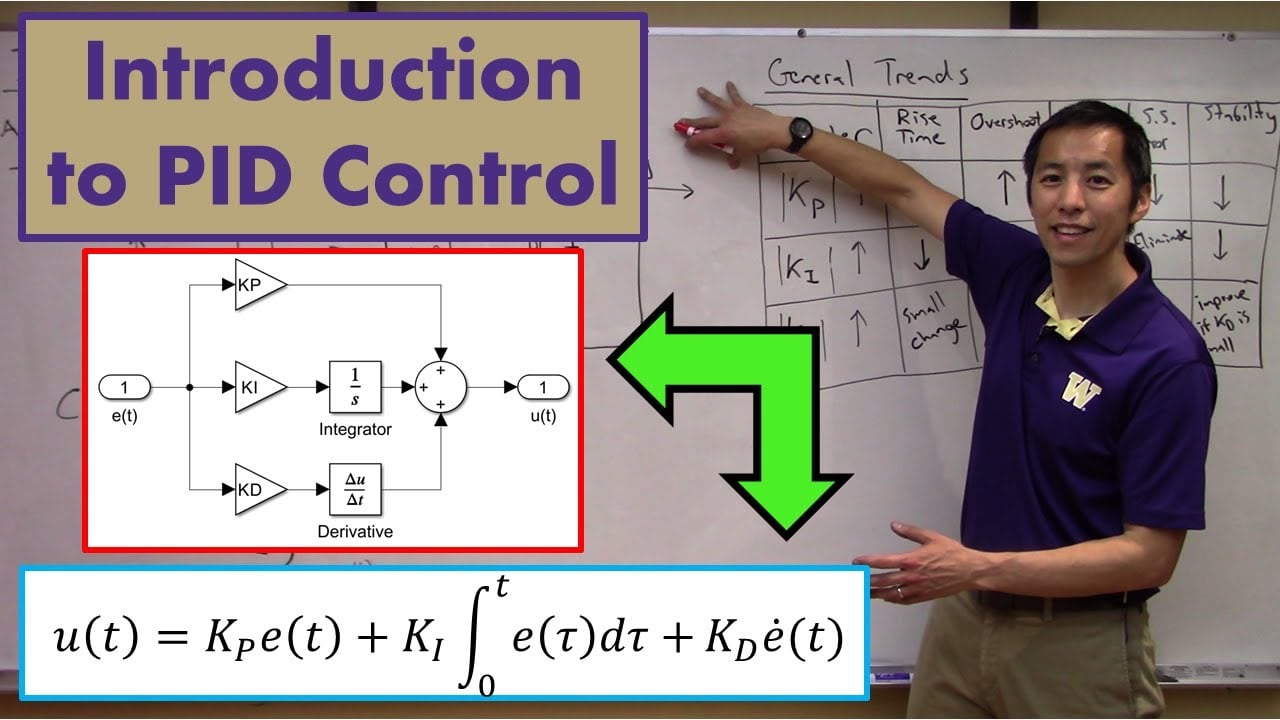
Christopher Lum’s PID educational video below explains the relationship between measurement, error and controller response. It provides control-theory background; it is not a wiring guide or a calibration procedure for the installed booster equipment.
Các câu hỏi thường gặp
Có đủ không khi khớp bộ điều khiển với đồng hồ gần nhất?
No. Confirm that both measure comparable pressure at understood locations and that the reference is suitable. Agreement at one point can conceal range errors elsewhere. Preserve multiple comparison points and the documented acceptance basis.
Có thể tiêm dòng điện để hiệu chuẩn cảm biến áp suất không?
Nó kiểm tra phần của chuỗi ở phía hạ lưu của điểm tiêm. Nếu phần tử áp suất bị bỏ qua, phản ứng của nó chưa được kiểm tra. Nêu rõ các thành phần nào đã được bao gồm và các thành phần nào đã bị loại trừ.
Có nên đặt cảm biến về không trong khi hệ thống đang được nén áp suất không?
Chỉ tuân theo phương pháp được xác định bởi nhà sản xuất dưới một sắp xếp thử nghiệm có kiểm soát. Áp suất của hệ thống sống không phải là tham chiếu bằng không. Loại cảm biến có ý nghĩa, đặc biệt khi phân biệt giữa áp suất đồng hồ và áp suất tuyệt đối.
Có cần kiểm tra bộ điều khiển cho một bộ phát mới không?
Có. Xác minh phạm vi, loại tín hiệu, đơn vị và khả năng tương thích cấu hình, sau đó so sánh chỉ báo đã lắp đặt và phản hồi chức năng. Một phụ kiện có thể thay thế về mặt vật lý không thiết lập khả năng tương thích điện hoặc đo lường.
Thì sao nếu hiệu chuẩn đạt nhưng áp suất vẫn không ổn định?
Giữ hồ sơ đo lường hợp lệ và điều tra nhu cầu thủy lực, phản ứng cảm biến, thiết lập giai đoạn và điều khiển một cách riêng biệt. Một lần hiệu chuẩn đạt yêu cầu không chứng minh rằng toàn bộ hệ thống bơm được chọn hoặc điều chỉnh đúng cách.