
An installation diagram defines mounting, connections, and scope split — not just pump model. Use this checklist when reviewing a water booster pump installation diagram before quotation or site work. For general layout symbols, see water booster pump diagram.
Contents
- Part 1. What Is an Installation Diagram Supposed to Clarify?
- Part 2. How Should Suction and Discharge Be Shown?
- Part 3. What Mounting and Base Details Matter?
- Part 4. How Are Controls and Power Shown?
- Part 5. Which Clearances and Maintenance Paths Should Be Checked?
- Part 6. Which BORRAPUMP Products Fit Installation Discussions?
- Part 7. What Are the Fit Boundaries?
- FAQ
Part 1. What Is an Installation Diagram Supposed to Clarify?
A water booster pump installation diagram answers site questions that a simple hydraulic sketch leaves open:
| Question class | Examples on the drawing | If missing |
|---|---|---|
| Physical placement | Mechanical room, skid location, elevation | Clash with equipment later |
| Connection points | Suction/discharge flange size and orientation | Wrong prefab spools |
| Support | Base bolts, inertia pad, vibration isolation | Warranty or noise issues |
| Electrical | Panel feed, motor disconnect, sensor wiring | Commissioning delay |
| Service space | Lift clearance, valve access, panel door swing | Maintenance blocked |
Compare with the procedural notes in booster pump installation — that article covers execution steps; this one covers drawing review before work starts.
Part 2. How Should Suction and Discharge Be Shown?
| Connection item | What to verify on the diagram | Field risk |
|---|---|---|
| Suction flange size and rating | Matches header and pump catalog | Cavitation, noise, NPSH margin loss |
| Suction isolation valve | Accessible for service | Cannot maintain pump |
| Straight run before suction | Manufacturer minimum if noted | Turbulence and seal issues |
| Discharge check valve | Orientation arrow shown | Water hammer or reverse rotation |
| Discharge isolation | Isolated for pump removal | Extended downtime |
| Flexible vs rigid couplings | Shown at pump flanges | Misalignment on startup |
Hydraulic Institute guidance applies: installation quality affects whether the pump can hold the duty point shown on the curve.
Part 3. What Mounting and Base Details Matter?
| Mounting element | Diagram should indicate | Why installers care |
|---|---|---|
| Skid or base frame | Anchor bolt pattern | Seismic or vibration requirements |
| Leveling pads | Shims or grouting note | Shaft alignment |
| Pump orientation | Vertical vs horizontal | Piping and venting |
| Panel stand or wall mount | Clearances | Code working space |
| Drain paths | Floor drain or drip leg | Housekeeping and freeze risk |
Packaged booster skids often ship with most valves on the manifold — the installation diagram should mark field-connected flanges versus factory-mounted components.
Part 4. How Are Controls and Power Shown?
| System | Typical diagram callouts | Scope check |
|---|---|---|
| Motor power feed | Voltage, phase, disconnect location | By electrician or included? |
| VFD / controller | Panel dimensions, ventilation | Indoor enclosure rating |
| Pressure transducer | Tap location and conduit route | Matches hydraulic diagram |
| Alarm outputs | BMS or fire alarm interface | Shown or note only |
| Grounding | Bonding to building ground | Often site responsibility |
Misaligned control diagrams are a common reason quoted packages exclude electrical installation — confirm scope before comparing prices in the booster pump price guide.

Part 5. Which Clearances and Maintenance Paths Should Be Checked?
| Clearance type | Minimum review | Typical problem |
|---|---|---|
| Pump removal space | Length of pump + coupling | Cannot pull motor or seal |
| Valve handle swing | 90° operation without obstruction | Cannot isolate |
| Panel door | Full open against wall | Cannot reset controller |
| Lifting route | Hoist or forklift path to room | Delivery stuck at door |
| Spare parts shelf | Seal kit storage near unit | Longer outages |
Installation diagrams that omit clearance dimensions should be flagged as layout concepts until the engineer adds measurable details.
Part 6. Which BORRAPUMP Products Fit Installation Discussions?
| Site layout signal | BORRAPUMP route | Installation note |
|---|---|---|
| Packaged skid in plant room | Booster Regulator Water Supply Equipment | Confirm anchor and flange interface |
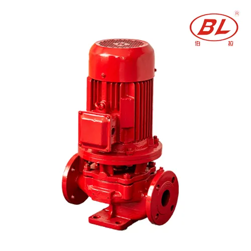
| Inline header installation | ISG Vertical Inline Boost Water Pump | Review pipe support and alignment |
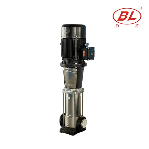
| Multistage higher head | CDL(F) Vertical Multistage Jockey Pump | Verify vertical service clearance |
RFQ checklist with installation diagram
| Data item | Why the supplier needs it |
|---|---|
| Marked installation drawing | Confirms interface points |
| Mechanical room dimensions | Validates skid or inline fit |
| Power available at location | Matches motor and panel |
| Desired furnished scope | Manifold, valves, panel inclusion |
| Destination and delivery constraints | Export crating and move-in path |
Part 7. What Are the Fit Boundaries?
This article supports installation diagram review for building water boosters. It does not certify seismic design, electrical code compliance, or final authority approval.
Fire pump, well, and sewage installations follow different drawing standards and product families — route those inquiries separately.
Relevant BORRAPUMP starting points
- Booster Regulator Water Supply Equipment
- ISG Vertical Inline Boost Water Pump
- CDL(F) Vertical Multistage Jockey Pump
For a quotation discussion, send measured duty point, source condition, control preference, and documentation requirements through contact Borra.
Fit Boundary
Do not treat a layout sketch as permission to install without local code, engineer review, and verified product instructions.
FAQ
What is the difference between a layout diagram and an installation diagram?
A layout diagram shows hydraulic order; an installation diagram adds mounting, connections, power, and clearances.
Who furnishes the isolation valves on a packaged booster?
It depends on the quote — the installation diagram should mark factory-mounted versus field-supplied items.
Does the installation diagram replace the manufacturer manual?
No. Use the manual for torque, alignment, startup, and warranty requirements.
What suction details matter most on the install drawing?
Flange size, isolation, support, and any required straight run before the pump.
Should electrical wiring appear on the booster install diagram?
Power and control interfaces should at least be referenced, even if detailed wiring is on separate sheets.
How much service clearance should a diagram show?
Enough for seal service, valve operation, and pump removal — exact dimensions come from the engineer or manufacturer.
Can I install from a marketing layout only?
No. Request a project-specific installation or GA drawing before fabrication and pour work.
What should I send BORRAPUMP with an installation diagram?
Send the drawing, room dimensions, duty point, power supply, and desired supply scope.