
A water booster pump diagram is read from source to outlet, not from the pump label alone. This guide explains how to read a building water booster layout using component tables, without treating a supplier sketch as the full project drawing. For the cluster overview, see the Booster Pumps guide.
Contents
- Part 1. What Should a Water Booster Pump Diagram Show?
- Part 2. How Do You Trace Flow on the Diagram?
- Part 3. Where Do Tanks, Sensors, and Controllers Appear?
- Part 4. Packaged Skid vs Inline Mechanical Room Layout
- Part 5. Which Diagram Reading Mistakes Cause Field Disputes?
- Part 6. Which BORRAPUMP Products Match Common Diagram Routes?
- Part 7. What Are the Fit Boundaries?
- FAQ
Part 1. What Should a Water Booster Pump Diagram Show?
A water booster pump diagram should make the hydraulic path visible from the water source to the building distribution header. At minimum, it should distinguish:
| Layer | What the reader needs to see | Why it matters |
|---|---|---|
| Source boundary | Municipal entry, break tank, or storage outlet | Defines inlet pressure and flow availability |
| Suction assembly | Isolation, strainer if shown, suction pipe | Service access and net inlet condition |
| Booster pump | Single or staged pumps on curve duty | Core pressure-add equipment |
| Discharge protection | Check valve, isolation, PRV if applicable | Prevents reverse flow and defines control boundary |
| Control branch | Tank tee, transducer tap, gauge, controller | Explains how pressure is regulated |
| Building header | Outlet to zones, floors, or equipment | Connects booster to system curve |
Hydraulic Institute material treats booster selection as a system problem — the diagram is useful only when it shows how the pump connects to that system, not when it shows an isolated pump icon.
Part 2. How Do You Trace Flow on the Diagram?
Read the diagram in the same order water moves during normal operation:
- Source to suction flange — confirm flooded suction or stable inlet pressure.
- Through the pump — identify single, parallel, or staged pumps.
- Through discharge check valve — note direction and service access.
- Into tank branch or sensor tap — see Part 3 for control differences.
- Out to the building header — follow to the point where residual pressure matters.
| Symbol / line type | Usually represents | Review question |
|---|---|---|
| Bold horizontal header | Main distribution pipe | Diameter and material noted? |
| Branch to bladder tank | Pressure storage / drawdown | Tank on controlled side? |
| Dashed control line | Sensor, switch, or VFD signal | Which pressure reference? |
| Bypass loop | Service or minimum flow | Does it defeat check protection? |
| Drain / test port | Commissioning and maintenance | Shown with isolation? |
If the drawing omits the inlet condition at peak flow, cross-check residential booster pump selection before assuming the layout fits the building.
Part 3. Where Do Tanks, Sensors, and Controllers Appear?
Diagrams differ mainly by control strategy:
| Control type | Typical diagram elements | Reader focus |
|---|---|---|
| Constant-speed with pressure switch | Tank, switch, pump start/stop | Cut-in/cut-out relative to tank pre-charge |
| VFD with transducer | Sensor tap, drive, optional small tank | Stable outlet pressure across demand swings |
| Packaged booster set | Skid, manifold, integrated panel | Supplier scope vs site piping |
Armstrong domestic booster guidance describes packaged boosting as a combined hydraulic and controls decision. On the diagram, the tank branch should sit where it can buffer the pressure the controller protects — not isolated by a closed check valve on the wrong side.
For tank-specific symbol reading, see the sibling article on booster pump with pressure tank diagram.
Part 4. Packaged Skid vs Inline Mechanical Room Layout
Two common diagram styles appear in export projects:
| Layout style | Diagram signal | Installation implication |
|---|---|---|
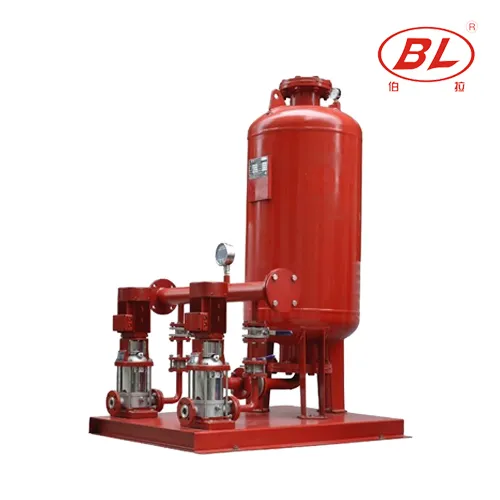
| Packaged booster skid | Pumps, panel, valves on one base | Vendor furnishes manifold; site connects suction/discharge |
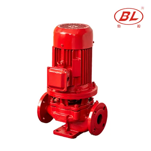
| Inline pump in plant room | Pump flanged into header | More site piping; tighter building-fit review |
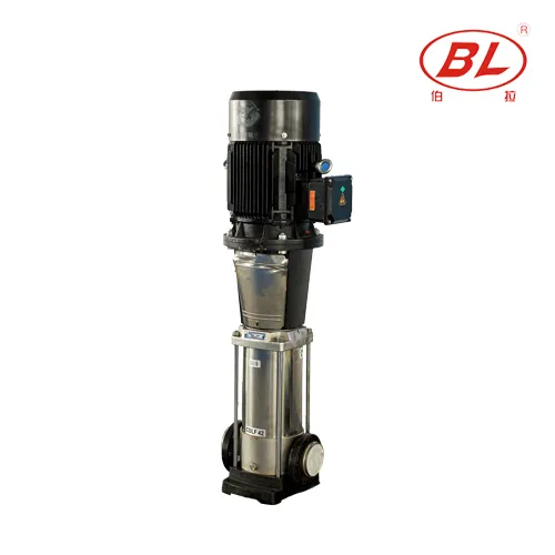
| Vertical multistage inline | Compact footprint in plant | Confirm NPSH and service clearance |
Neither style replaces the engineer's calculation of required flow and head. The diagram helps the buyer confirm scope — who furnishes valves, gauges, controller, and test points — before comparing quotations.
Part 5. Which Diagram Reading Mistakes Cause Field Disputes?
| Mistake | Why it causes rework | Better review step |
|---|---|---|
| Treating concept art as install drawing | Missing elevations, anchors, electrical | Request GA drawing with notes |
| Ignoring inlet pressure annotation | Pump sized for wrong boost head | Match diagram to hydraulic calc |
| Mixing irrigation and building boost symbols | Wrong product family | Confirm medium and code context |
| Assuming tank is included | Scope gap at commissioning | Mark furnished vs by-others items |
| Copying a neighbor's layout | Different curve and demand | Plot project duty point |
Pumps & Systems editorial coverage of pumping packages emphasizes that accessories shown in marketing layouts are often optional in commercial quotes.
Part 6. Which BORRAPUMP Products Match Common Diagram Routes?
| Diagram signal | BORRAPUMP route | Notes |
|---|---|---|
| Packaged building water boost | Booster Regulator Water Supply Equipment | Confirm inlet and target pressure |
| Inline booster in header | ISG Vertical Inline Boost Water Pump | Review mechanical-room fit |
| Higher-head multistage duty | CDL(F) Vertical Multistage Jockey Pump | Match staged head to curve |
RFQ checklist when sending a diagram
| Data item | Why the supplier needs it |
|---|---|
| Marked-up diagram or photo | Confirms intended layout |
| Flow and outlet pressure | Sizes duty point |
| Inlet pressure at peak flow | Defines boost head |
| Control preference | Sets panel and sensor scope |
| Furnished vs site-installed items | Prevents scope disputes |
Part 7. What Are the Fit Boundaries?
A water booster pump diagram supports layout discussion and procurement scope. It does not approve the installation, certify compliance, or replace the project engineer's fire-protection or plumbing documents when those systems are involved.
Keep fire-pump, well-lift, and sewage duties on their own product routes. This article stays within the Water Supply Booster Pump cluster.
Relevant BORRAPUMP starting points
- Booster Regulator Water Supply Equipment
- ISG Vertical Inline Boost Water Pump
- CDL(F) Vertical Multistage Jockey Pump
For a quotation discussion, send measured duty point, source condition, control preference, and documentation requirements through contact Borra.
Fit Boundary
Do not treat a concept diagram as code-approved construction documentation. Do not claim UL/FM/NFPA listing without verified certificates.
FAQ
What is the first component to find on a water booster pump diagram?
Start at the water source or break-tank outlet, then follow the suction line to the pump.
Where does the check valve go on a booster diagram?
Most layouts show a discharge check valve after the pump and before the tank branch or header, but follow the project drawing.
Does every booster diagram include a pressure tank?
No. VFD systems may use a smaller tank or none; constant-speed switch systems more often show a tank branch.
What is the difference between a diagram and an installation drawing?
A diagram explains layout logic; an installation drawing adds dimensions, anchors, elevations, and code-specific details.
Can I use a supplier diagram for permit submission?
Only if the supplier or engineer issues it as a project-specific document accepted by the authority having jurisdiction.
How do packaged and inline boosters look different on diagrams?
Packaged sets show a skid with pumps, valves, and panel; inline layouts show the pump flanged into existing plant headers.
What should I send BORRAPUMP with a diagram?
Send the diagram, duty point, inlet condition, control preference, and a list of furnished accessories.
Is this the same as a fire pump diagram?
No. Fire pump diagrams include jockey and approval scope that building water boosters do not share by default.