
Size an electric fire pump motor and select its starting method as one listed system with the pump and controller. The motor must carry the pump's required load across the applicable performance curve and start on the available electrical source without unacceptable voltage effects. Use the pump power curve, motor and controller listings, service factor rules where applicable, locked-rotor characteristics, conductor and transformer data, and emergency-power strategy. Do not use normal process-pump motor sizing shortcuts without checking fire-pump requirements. Keep the calculation and acceptance record with the final project documents so future tests use the same basis.
Safety and scope: Fire pumps and their drivers are life-safety equipment. Hydraulic, electrical, diesel, fuel, battery, pressure, rotating-equipment, testing, and impairment work must follow the current approved design, manufacturer instructions, applicable standards, and the authority having jurisdiction. This guide explains the engineering decision path; it does not authorize field changes, bypasses, or operation by unqualified personnel.
Use the complete pump power curve
Review brake power from churn through the required high-flow region. Confirm whether the selected impeller and speed can overload the proposed motor. Treat this as a system condition rather than an isolated component choice. Identify the source of every input, the unit used, the operating condition it represents, and the person responsible for approval. If information is preliminary, mark the assumption and test how the decision changes at a conservative boundary. This prevents a neat calculation from hiding an uncertain water level, pressure, valve position, driver condition, or simultaneous demand.
For fire pump motor sizing, verify this section against the selected pump curve, the actual site arrangement, manufacturer instructions, and the current requirements accepted by the authority having jurisdiction. Check the installed condition as well as the drawing because pipe routes, elevations, supports, controls, and access often change during construction. Record the result in a form that can be repeated during commissioning and later inspection. Do not change a safety-critical setting or isolate fire protection without the approved impairment and restoration process.
Match voltage, phase, and frequency
The motor, controller, utility, generator, and transfer arrangement must share compatible ratings and tolerate actual voltage conditions. The most useful evidence is measured or approved project data, not a copied rule of thumb. Identify the source of every input, the unit used, the operating condition it represents, and the person responsible for approval. If information is preliminary, mark the assumption and test how the decision changes at a conservative boundary. This prevents a neat calculation from hiding an uncertain water level, pressure, valve position, driver condition, or simultaneous demand.
For fire pump motor sizing, verify this section against the selected pump curve, the actual site arrangement, manufacturer instructions, and the current requirements accepted by the authority having jurisdiction. Check the installed condition as well as the drawing because pipe routes, elevations, supports, controls, and access often change during construction. Record the result in a form that can be repeated during commissioning and later inspection. Do not change a safety-critical setting or isolate fire protection without the approved impairment and restoration process.
Understand starting current
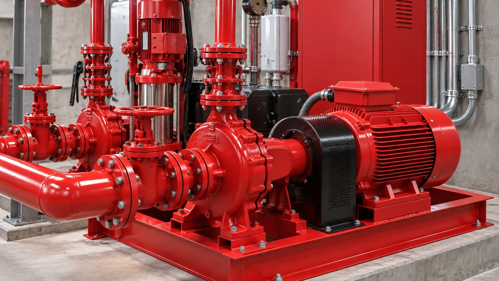
Across-the-line starting is simple but can create a large voltage dip. Reduced-voltage methods change current and torque and must be approved for the application. Review this condition at normal, test, and credible abnormal states before procurement. Identify the source of every input, the unit used, the operating condition it represents, and the person responsible for approval. If information is preliminary, mark the assumption and test how the decision changes at a conservative boundary. This prevents a neat calculation from hiding an uncertain water level, pressure, valve position, driver condition, or simultaneous demand.
For fire pump motor sizing, verify this section against the selected pump curve, the actual site arrangement, manufacturer instructions, and the current requirements accepted by the authority having jurisdiction. Check the installed condition as well as the drawing because pipe routes, elevations, supports, controls, and access often change during construction. Record the result in a form that can be repeated during commissioning and later inspection. Do not change a safety-critical setting or isolate fire protection without the approved impairment and restoration process.
Compare starting methods
Review full-voltage, autotransformer, primary resistor or reactor, part-winding, wye-delta, and approved solid-state arrangements according to the specific system and listing. The design team should turn this point into a traceable calculation or drawing note. Identify the source of every input, the unit used, the operating condition it represents, and the person responsible for approval. If information is preliminary, mark the assumption and test how the decision changes at a conservative boundary. This prevents a neat calculation from hiding an uncertain water level, pressure, valve position, driver condition, or simultaneous demand.
For fire pump motor sizing, verify this section against the selected pump curve, the actual site arrangement, manufacturer instructions, and the current requirements accepted by the authority having jurisdiction. Check the installed condition as well as the drawing because pipe routes, elevations, supports, controls, and access often change during construction. Record the result in a form that can be repeated during commissioning and later inspection. Do not change a safety-critical setting or isolate fire protection without the approved impairment and restoration process.
Practical decision table
| Starting option | Main benefit | Key review |
|---|---|---|
| Full-voltage | Simple and high starting torque | Source voltage dip and capacity |
| Autotransformer | Reduced line current | Approved taps, transition, and torque |
| Primary resistor/reactor | Reduced starting current | Voltage, heat, torque, transition |
| Part-winding | Uses suitable motor winding design | Motor compatibility and sequence |
| Wye-delta | Reduced current with specific motor | Lead arrangement and torque |
| Approved solid-state method | Controlled electrical transition | Listing, bypass, heat, and reliability |
Check source capacity and voltage drop
Model utility or generator impedance, transformer, conductors, starting current, simultaneous loads, and minimum acceptable terminal voltage. Treat this as a system condition rather than an isolated component choice. Identify the source of every input, the unit used, the operating condition it represents, and the person responsible for approval. If information is preliminary, mark the assumption and test how the decision changes at a conservative boundary. This prevents a neat calculation from hiding an uncertain water level, pressure, valve position, driver condition, or simultaneous demand.
For fire pump motor sizing, verify this section against the selected pump curve, the actual site arrangement, manufacturer instructions, and the current requirements accepted by the authority having jurisdiction. Check the installed condition as well as the drawing because pipe routes, elevations, supports, controls, and access often change during construction. Record the result in a form that can be repeated during commissioning and later inspection. Do not change a safety-critical setting or isolate fire protection without the approved impairment and restoration process.
Coordinate controller and protection
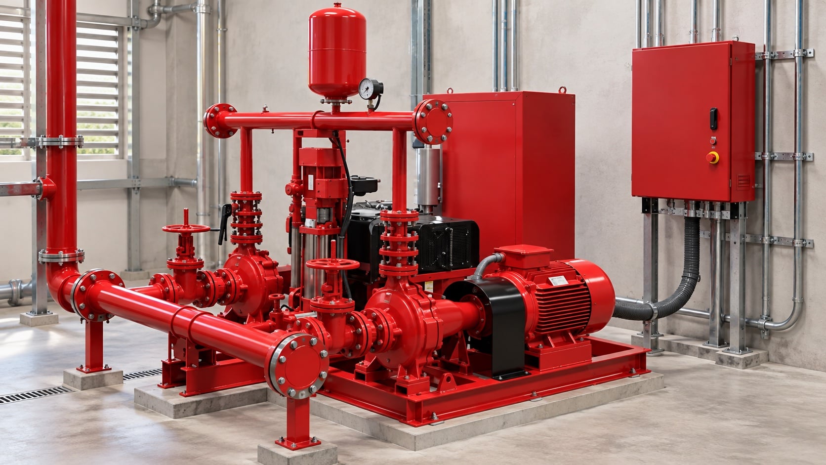
Fire pump controllers have a specialized operating purpose. Do not apply ordinary motor protection or shutdown logic that could prevent required operation. The most useful evidence is measured or approved project data, not a copied rule of thumb. Identify the source of every input, the unit used, the operating condition it represents, and the person responsible for approval. If information is preliminary, mark the assumption and test how the decision changes at a conservative boundary. This prevents a neat calculation from hiding an uncertain water level, pressure, valve position, driver condition, or simultaneous demand.
For fire pump motor sizing, verify this section against the selected pump curve, the actual site arrangement, manufacturer instructions, and the current requirements accepted by the authority having jurisdiction. Check the installed condition as well as the drawing because pipe routes, elevations, supports, controls, and access often change during construction. Record the result in a form that can be repeated during commissioning and later inspection. Do not change a safety-critical setting or isolate fire protection without the approved impairment and restoration process.
Plan generator operation
If an alternate source is used, verify starting and running capacity, transfer sequence, fuel, ventilation, and the effect of other emergency loads. Review this condition at normal, test, and credible abnormal states before procurement. Identify the source of every input, the unit used, the operating condition it represents, and the person responsible for approval. If information is preliminary, mark the assumption and test how the decision changes at a conservative boundary. This prevents a neat calculation from hiding an uncertain water level, pressure, valve position, driver condition, or simultaneous demand.
For fire pump motor sizing, verify this section against the selected pump curve, the actual site arrangement, manufacturer instructions, and the current requirements accepted by the authority having jurisdiction. Check the installed condition as well as the drawing because pipe routes, elevations, supports, controls, and access often change during construction. Record the result in a form that can be repeated during commissioning and later inspection. Do not change a safety-critical setting or isolate fire protection without the approved impairment and restoration process.
Test the integrated system
Witness starting on each source, transfer where applicable, current, voltage, rotation, controller alarms, and pump performance without unauthorized trips. The design team should turn this point into a traceable calculation or drawing note. Identify the source of every input, the unit used, the operating condition it represents, and the person responsible for approval. If information is preliminary, mark the assumption and test how the decision changes at a conservative boundary. This prevents a neat calculation from hiding an uncertain water level, pressure, valve position, driver condition, or simultaneous demand.
For fire pump motor sizing, verify this section against the selected pump curve, the actual site arrangement, manufacturer instructions, and the current requirements accepted by the authority having jurisdiction. Check the installed condition as well as the drawing because pipe routes, elevations, supports, controls, and access often change during construction. Record the result in a form that can be repeated during commissioning and later inspection. Do not change a safety-critical setting or isolate fire protection without the approved impairment and restoration process.
How this relates to BORRAPUMP equipment
BORRAPUMP supplies engineered pump equipment for water and fire-protection projects. Review the relevant BORRAPUMP product configuration as a starting point, then submit the required flow, head, water source, driver, power, controls, site conditions, applicable requirements, quantity, and destination. Final selection must use the project hydraulic basis and approved submittal; this guide does not claim that one catalog arrangement fits every jurisdiction or risk.
Related BORRAPUMP guides
Authoritative references
The following sources establish the standards boundary, fire-safety context, and pump-system principles used in this guide. Always apply the edition and local adoption accepted for the project.
- NFPA 20 standard development page
- U.S. Department of Energy pump systems resources
- NIST fire protection research
Educational video
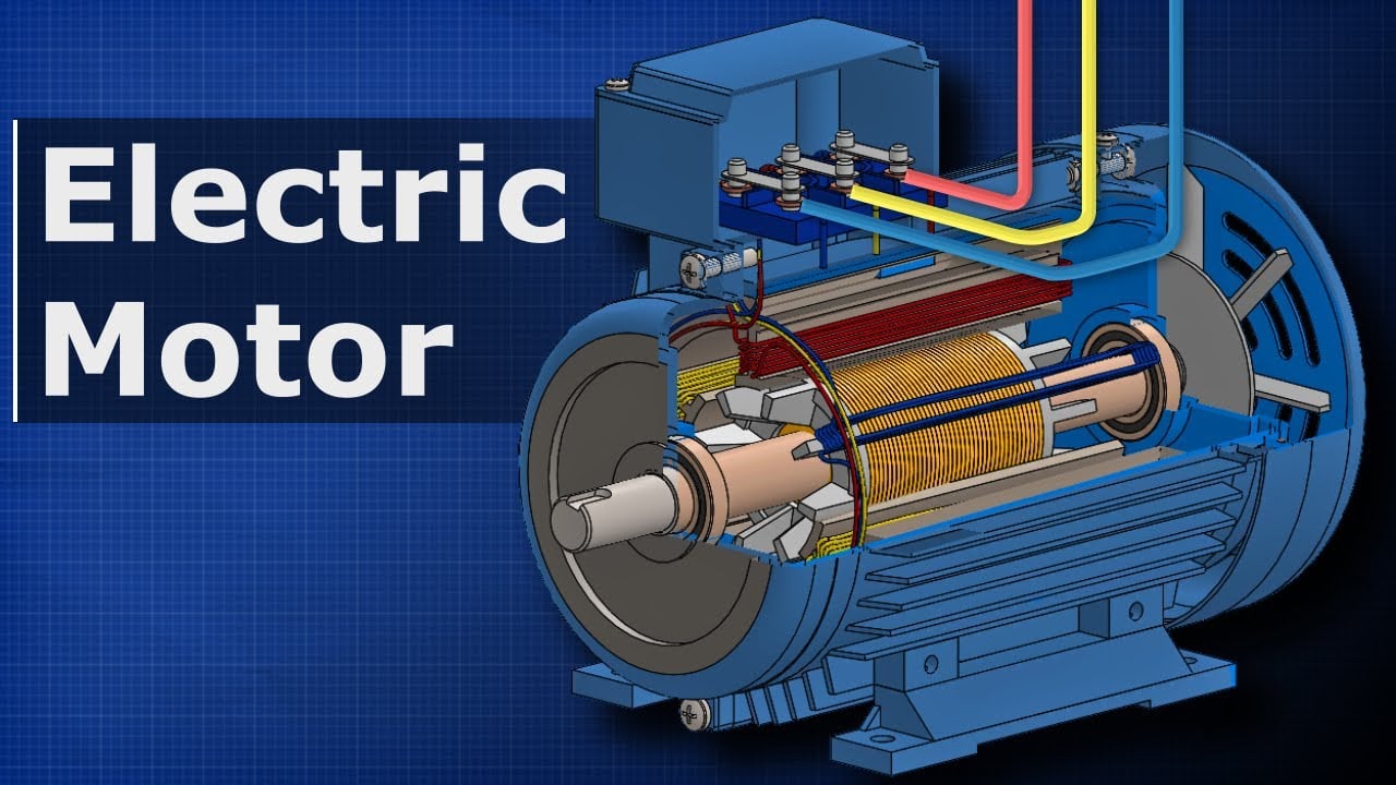
Educational background by The Engineering Mindset: How Electric Motors Work: Three-Phase AC Induction Motors. The video supports the underlying engineering concept and does not replace project-specific fire-protection requirements.
Frequently asked questions
Can I size the motor only at rated pump flow?
No. Review the applicable pump power curve and the requirements governing motor selection across the operating range.
Is a soft starter always best?
No. The starting method must be approved, reliable, and compatible with motor torque, source capacity, controller, and project requirements.
Why check generator voltage dip?
Low voltage during starting can prevent acceleration or disturb other emergency loads.
Can normal overload protection stop a fire pump?
Fire pump controller protection and operating logic are specialized. Follow the approved listed arrangement.
Final verification checklist
Before approval, confirm the hydraulic basis, water-source condition, selected pump curve, driver and controller data, component pressure ratings, valve arrangement, test method, access, drainage, alarms, and restoration procedure. Resolve differences between drawings and the installed system. During commissioning, use calibrated instruments and record suction pressure, discharge pressure, flow, speed, driver condition, alarms, and abnormal observations at every required point. Keep the accepted results with the pump-room records so later inspections compare like with like.