A submersible sewage pump guide-rail installation provides a controlled path for lowering and retrieving a compatible pump, usually with a documented discharge coupling at the bottom of the wet well. Successful installation depends on matched components, alignment, structural supports, lifting clearance and safe access. Guide rails do not prove that any sewage pump will fit an automatic coupling. Obtain the selected pump and accessory drawings before purchasing or building the arrangement. This guide explains the coordination and inspection process; it does not replace the supplier’s installation manual or authorize entry into a wastewater chamber.
Confirm the complete assembly before construction
Identify the exact pump model, discharge connection, guide attachment, bottom coupling, rail arrangement, upper bracket and lifting method. Ask whether these components are supplied as a verified system or selected separately by the contractor. Confirm the working interface on drawings, including dimensions and permitted tolerances. Matching nominal pipe size alone does not demonstrate that a pump will engage and seal correctly.
Das Borra WQ submersible sewage pump is the relevant product family for a sewage duty discussion. Its product image is not an accessory schedule. Request written confirmation of the specific coupling, guide hardware and lifting arrangement offered with the chosen model. Do not manufacture an improvised shoe or alter the pump housing to make it fit an unrelated coupling.
Record which party owns each interface: pump supplier, mechanical installer, civil contractor and electrical contractor. Resolve missing brackets, anchor details, cable supports and lifting equipment before the wet well is completed. Late changes can reduce service clearance or require rework to a structure that should remain watertight.
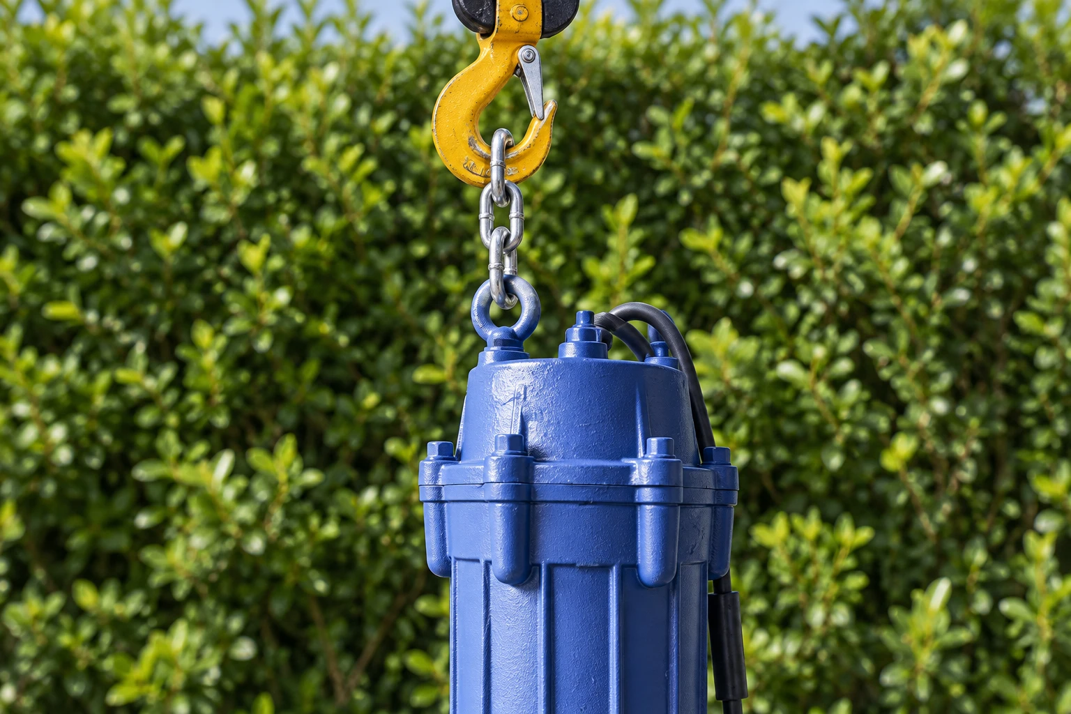
Check the wet-well drawing and removal envelope
A pump must fit through the hatch and travel along its retrieval path without striking inlet pipes, floats or structural members. Check the pump’s complete envelope, including guide attachment and lifting fittings. Review hatch opening, rail spacing, basin depth and clearance above the cover for the lifting equipment. A clear path on plan can still fail in section when the hoist cannot lift the pump high enough.
Confirm the discharge route, location of isolation valves and access to the non-return valve. Maintenance personnel should be able to identify and isolate the relevant equipment without improvising around an open chamber. Consider where the removed pump will be set down, cleaned and examined. Provide a stable service area appropriate to the station and the contaminated equipment.
Das EPA in-plant pump-station fact sheet gives context for the surrounding pump, wet-well, controls and service equipment. Use the site-specific design for actual structural dimensions and loads; a general guidance document cannot size an anchor or certify a lifting beam.
Install the base coupling to the approved details
Check the concrete condition, mounting surface and anchor layout against the issued drawings. Set the base assembly at the specified orientation and elevation. Verify that the discharge pipe will connect without forcing the coupling out of position. Pipe loads should be carried by the designed supports, not transferred through the pump docking interface because a route was installed slightly out of alignment.
Use the specified anchorage and tightening procedure. Anchor suitability depends on the concrete, edge distance, embedment, environment and load case. Do not select fasteners from a generic online torque table or drill additional holes without design approval. Record the installed parts and any authorized deviations so later maintenance does not rely on uncertain assumptions.
Before the basin becomes difficult to access, inspect the coupling and pipe joint for correct assembly and sealing. Remove construction debris and verify that the pump’s landing area is unobstructed. Use the project’s appropriate inspection and access procedure; an empty chamber can still be a confined-space hazard.
Align the rails over the entire travel
Rails need the position, spacing and support arrangement stated by the accessory manufacturer. Check alignment along the full length rather than only at the hatch. A bracket that looks correct at the top may force the rails sideways near the base or bind the pump attachment. Verify intermediate supports where the documented arrangement requires them.
Inspect rail surfaces and joints for burrs, distortion or projections that could obstruct travel. Confirm materials suit the wastewater environment and the documented sliding interface. Do not substitute a convenient pipe section for the specified rail merely because its outside diameter seems close. Material stiffness, corrosion and fit can affect removal as well as installation.
After the supports are secured, perform the approved dry travel or trial fit where possible. Confirm that the pump moves freely and reaches its correct seated position. Resistance should be investigated rather than overcome with impact, excessive pull or an improvised additional load. Stop if the interface binds or the pump will not land as documented.
Route the cable independently of the lifting system
Use the designated lifting point and appropriately rated lifting equipment. The electrical cable is not a lifting line. Keep it clear of the guide path and provide the support, bend radius and strain relief specified for the installation. Account for the cable movement during retrieval so it cannot catch on the hatch, coupling or rail brackets.
Identify cables and provide the approved terminations and sealing arrangements. Electrical installation and testing belong to qualified personnel. The control design should include the relevant isolation and protection for maintenance. The official hazardous-energy control regulation explains the purpose of preventing unexpected energization during equipment service; the site’s applicable procedure must address the actual station.
Level devices also need independent clearance. Check their operating envelope with the pump in position and during removal. A lifting chain that hangs across a float path can defeat otherwise correct level settings. Read sewage pump float-switch placement when coordinating those interfaces.
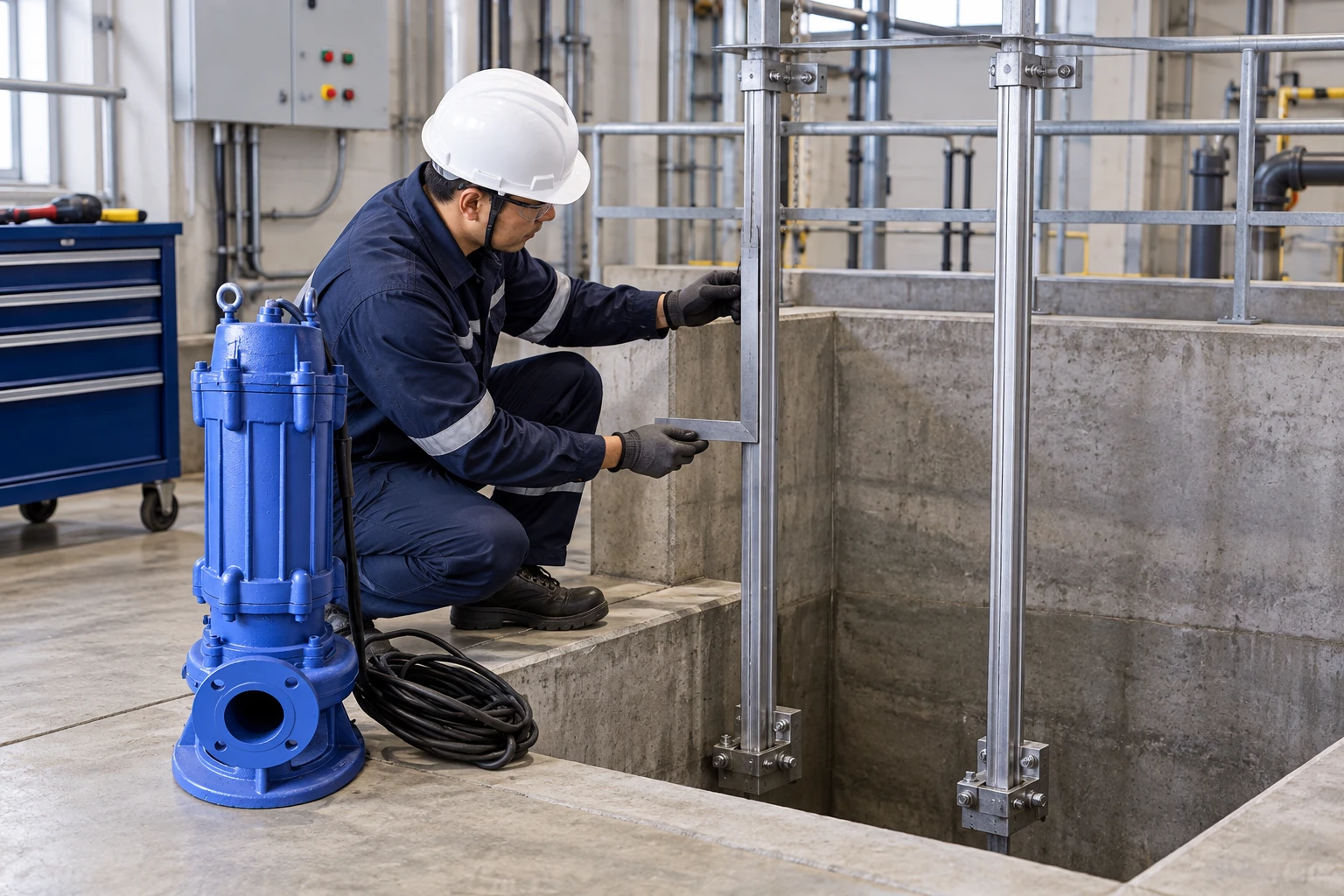
Use a practical inspection schedule
| Inspection | Beweise aufzeichnen | Issue to resolve before handover |
|---|---|---|
| Component match | Pump and accessory model drawings | Unverified docking interface |
| Structural support | Issued anchorage and bracket details | Missing or unauthorized support |
| Rail alignment | Full travel and trial-fit record | Binding, uneven spacing or distortion |
| Discharge connection | Pipe-support and joint inspection | Forced fit or loads on coupling |
| Retrieval access | Hatch and hoist clearance check | No safe removal or set-down space |
| Cable and levels | Cable support and float-clearance test | Cable used for lifting or devices obstructed |
This table is a coordination checklist. It intentionally gives no universal dimensions, rail sizes, anchor loads or tightening values. Those must come from the approved assembly and project design. The submersible sewage pump sizing guide provides the hydraulic information that should accompany the mechanical layout.
Verify seating and station performance
Once the pump is installed, confirm that it has reached the documented seated position and that lifting equipment can be safely managed. Complete the approved checks before energizing. Observe the station’s delivered performance through its normal operating range and inspect for indications of an incomplete discharge connection. A pump motor running does not demonstrate that its coupling is fully engaged.
Test each installed pump and the relevant control sequence. Record working levels, measured duty and alarm behavior. In a duplex station, verify the retrieval arrangement for either pump without disturbing the other pump’s cable, guide path or level equipment. Review duplex sewage pump control for the operational checks that complement mechanical installation.
If flow differs from the approved selection, investigate valve position, system resistance, coupling seating and instrumentation. Do not immediately change pump speed or impeller size. Keep commissioning observations linked to the as-built drawings so a later operator can reproduce the test conditions.
Plan retrieval before the first breakdown
Prepare a documented removal procedure, equipment list and safe set-down location. Confirm whether the station needs temporary pumping or other continuity measures while a pump is removed. Store the accessory drawings, part references and inspection records where maintenance staff can access them. A guide-rail installation only delivers its service benefit when the retrieval process is usable.
Inspect lifting components, accessible rail supports and cable condition according to the approved maintenance plan. Corrosion, wear or a change in the surrounding installation can compromise a system that originally passed commissioning. Record any altered hatch, cable route or discharge support and review its effect on retrieval before the next service task.
For the broader equipment categories, see Abwasserpumpen-Typen before narrowing the selection to this station task.
Häufig gestellte Fragen
Will every submersible sewage pump fit a guide rail?
No. The pump attachment and discharge coupling must be compatible and documented. Confirm the exact model and accessory assembly instead of assuming that a shared discharge size establishes fit.
Can the electrical cable be used to retrieve the pump?
No. Use the pump’s designated lifting point and specified lifting arrangement. Support and protect the cable separately so retrieval does not damage the conductor, seal or termination.
What causes a pump to bind during lowering?
Possible causes include misaligned rails, distorted hardware, obstructed travel or an incorrect guide attachment. Stop and inspect the assembly. Forcing the pump down can damage the interface and conceal the underlying mismatch.
Which records should be handed over?
Provide the matched pump and accessory drawings, as-built layout, anchorage record, trial-fit and commissioning results, lifting procedure, cable details and maintenance instructions. Include approved changes rather than leaving them as undocumented site adjustments.
Weiterbildungen
This EPA educational session covers wastewater operator calculations, including pump flow and wet-well volume. Use it to understand the quantitative checks in this guide; it does not replace the selected station design or device manual.