
Pump soft foot correction starts by finding why a mounting foot does not make stable contact with its support. Clean and inspect the contact surfaces, measure movement under a controlled bolt sequence, distinguish a simple gap from angular contact or external loading, and correct the cause before final shaft alignment. Adding shims until an alignment display turns green does not prove that the machine frame is supported correctly. Use the equipment manufacturer’s acceptance limits and installation procedure for the particular pump and driver.
This guide is for maintenance teams inspecting separately mounted industrial water pumps and motors. Close-coupled, vertical, monobloc and special mounting arrangements require their own instructions. It does not provide a universal soft-foot tolerance or permission to modify a casing, mounting foot or structural base.
Establish what is moving and what the measurement means
Soft foot concerns the support of a machine frame. When a foot bolt is tightened, uneven support can pull the frame away from its relaxed position. A movement reading at the shaft, the top of a foot, or the alignment instrument may show the consequence of this distortion. Those readings are not automatically the physical gap beneath the foot.
Mark the four mounting positions on a sketch and identify the measuring location. Record whether the observation is vertical lift, a contact gap, or a shaft movement. This distinction matters when a large shaft response is produced by a small support defect. It also prevents a technician from inserting a shim equal to a displayed movement without checking the actual contact geometry.
A general overview of measurement tools is available in our pump shaft alignment methods guide. The task here is to stabilize the support before that final alignment process, rather than compare alignment instruments again.
Make the inspection safe and repeatable
Isolate the driver and verify that unexpected starting is prevented under the site’s energy-control procedure. Address stored hydraulic energy, automatic controls and any hazardous liquid before removing guards or loosening fasteners. Do not inspect mounting contact by reaching into an operating assembly. A stopped motor is not sufficient evidence of isolation.
Identify which fasteners can be loosened and in what sequence. A large assembly may need a lifting or support plan before its supports are disturbed. Review coupling restrictions and the condition of connected pipework. If the pump is carrying pipe weight, a foot test may expose a movement that cannot safely be corrected by shimming alone.
Use a stable measurement setup, label each bolt and start from a documented tightening condition. Keep the same instrument position and procedure for repeat tests. Changes made between measurements should be recorded individually so that their effects remain understandable.
Inspect the mounting surfaces before calculating a correction
Remove loose contamination, damaged paint, burrs and unsuitable packing from accessible contact areas using the approved maintenance process. Inspect for cracked feet, corroded supports, distorted washers, damaged threads and poor bolt seating. A stack resting on dirt may compress during tightening and return an inconsistent reading even when its nominal thickness looks correct.
Check whether each shim supports the intended footprint. A small piece under only one edge may create a rocking contact. Avoid covering a damaged foundation with an increasingly complicated stack. If structural support, grout or anchor integrity is questionable, refer the defect for repair before treating it as an alignment adjustment.
For new or repaired foundations, the pump baseplate grouting inspection plan covers a different hold point: whether the base itself is properly installed. Soft-foot measurements cannot certify the condition of hidden grout or anchors.
Distinguish parallel gaps from angular contact
A reasonably uniform gap beneath a foot suggests a different correction from a wedge-shaped gap. Check contact at accessible positions around the foot with the measurement method allowed by the equipment procedure. Do not force a feeler gauge into a loaded interface and treat the resulting opening as an unloaded measurement.
Angular contact requires particular care. One corner may touch while the opposite side lifts, so a full-width parallel shim can improve one reading while increasing frame distortion elsewhere. Confirm the geometry and use an approved correction method. Machining, tapered corrections and changes to structural supports require competent review; they are not routine improvisations for every installer.
Acoem’s soft-foot educational resources explain why support defects can undermine repeatable alignment. Use these concepts with the manufacturer’s mounting instructions, rather than adopting a tolerance from an unrelated instrument demonstration.
Test one condition at a time
Follow the approved bolt-release sequence and observe how each location responds. Return the machine to the documented starting condition between comparisons. If several bolts are loosened without control, the assembly can redistribute its weight and hide which support produced the original problem.
Record the measurement direction and sign, not just its magnitude. Note whether movement repeats after retightening. Repeatability is valuable evidence: a reading that changes substantially on every attempt may indicate unstable instrument mounting, dirty interfaces, damaged fasteners or an unresolved external force.
If the coupling or connected pipework can influence the test, record its condition. Any permitted disconnection or release must follow the site procedure, with pressure removed and supports secured. Never use flange bolts to force piping into place merely to make a soft-foot reading appear smaller.
Use the observation to select the next action
The following table is a practical inspection aid, not a set of acceptance limits. Its actions depend on confirmed contact geometry and the approved mounting procedure.
| Observación | Qué verificar | Appropriate next action |
|---|---|---|
| Repeatable lift with a uniform accessible gap | Clean contact and stable base | Select an approved parallel shim correction and retest |
| Contact at one edge with a varying gap | Foot and support geometry | Refer angular correction for an approved method |
| Reading changes after each tightening cycle | Dirt, bolt seating and instrument stability | Restore a repeatable setup before choosing shim thickness |
| Movement changes when piping condition changes | Pipe supports and flange fit | Correct the external load through the installation team |
| Several feet respond unpredictably | Frame, base and support condition | Stop local adjustments and investigate the assembly |
Treat the table as a way to organize evidence. A single observation does not establish the full cause, particularly on a previously repaired machine with several interacting defects.
Control the shim stack and fasteners
Select shim material, dimensions and thicknesses suitable for the approved assembly. Keep a record of the final stack at each foot. Minimize unnecessary layers and ensure that shims remain properly positioned during tightening. A clean stack with an identifiable thickness is easier to inspect and reproduce during the next maintenance visit.
Use the specified fasteners, washers, tightening method and sequence. Do not use extra bolt force to pull a poorly supported frame down onto the base. If a bolt bottoms out or its washer bears on a damaged surface, the apparent tightening result may be misleading.
After a correction, repeat the support check before making final alignment moves. Where the correction shifts the machine height or position, update the alignment record. A support correction and a shaft alignment correction are related operations, but their acceptance evidence should remain identifiable.
Check external forces and assembly changes
Piping, conduit, brackets and auxiliary tubing can restrain a machine. Look for attachments that were installed after the original alignment. Confirm that supports carry their intended loads and that maintenance changes have not created a new restraint. Do not assume a flexible connector removes every force under all operating conditions.
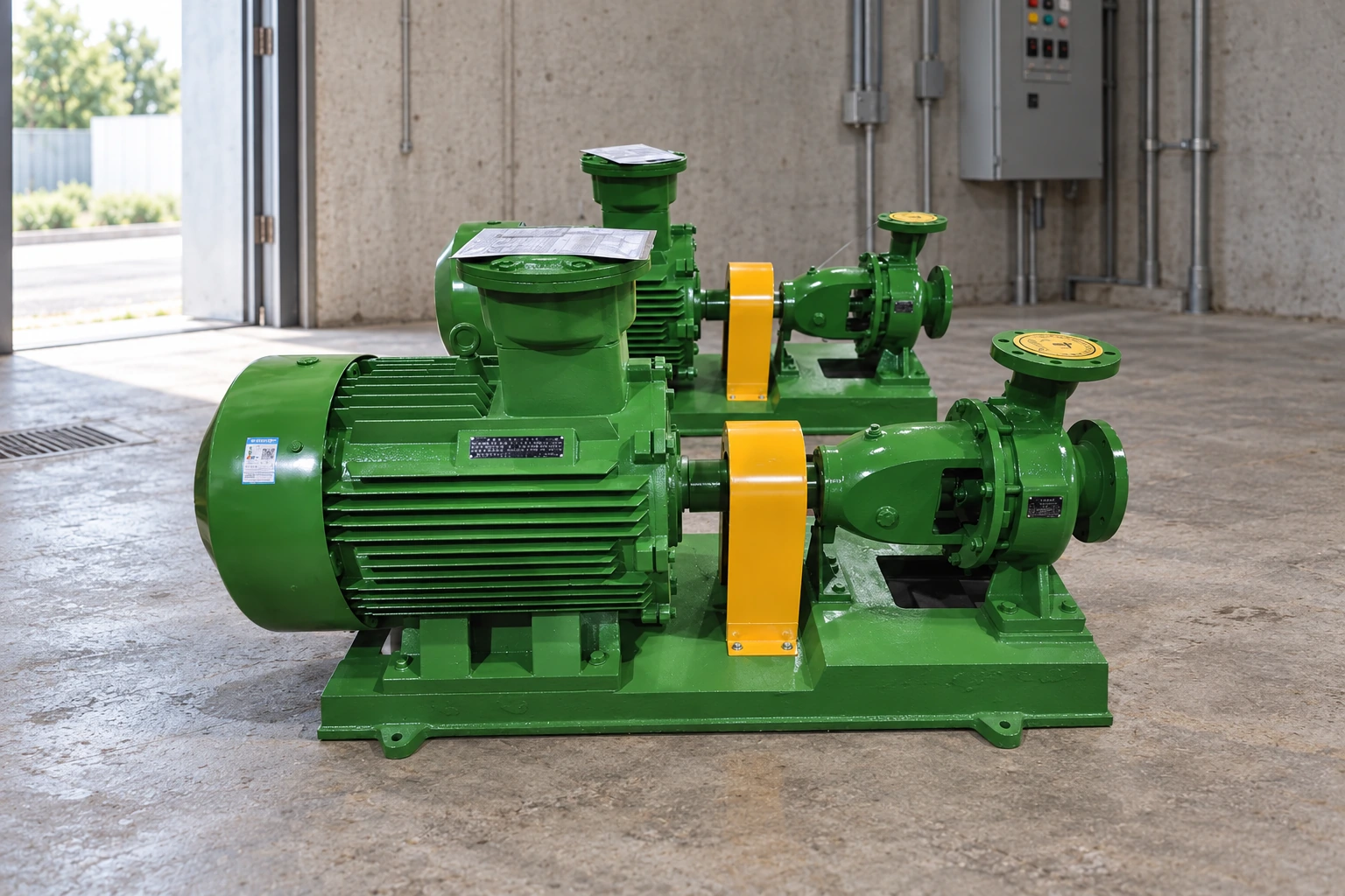
For an IS clean-water centrifugal pump installation, request the actual assembly drawing and mounting instructions before applying a correction. The product photograph identifies the pump family; it does not establish the installed foot geometry, permissible nozzle loads or shim limits of a particular delivered unit.
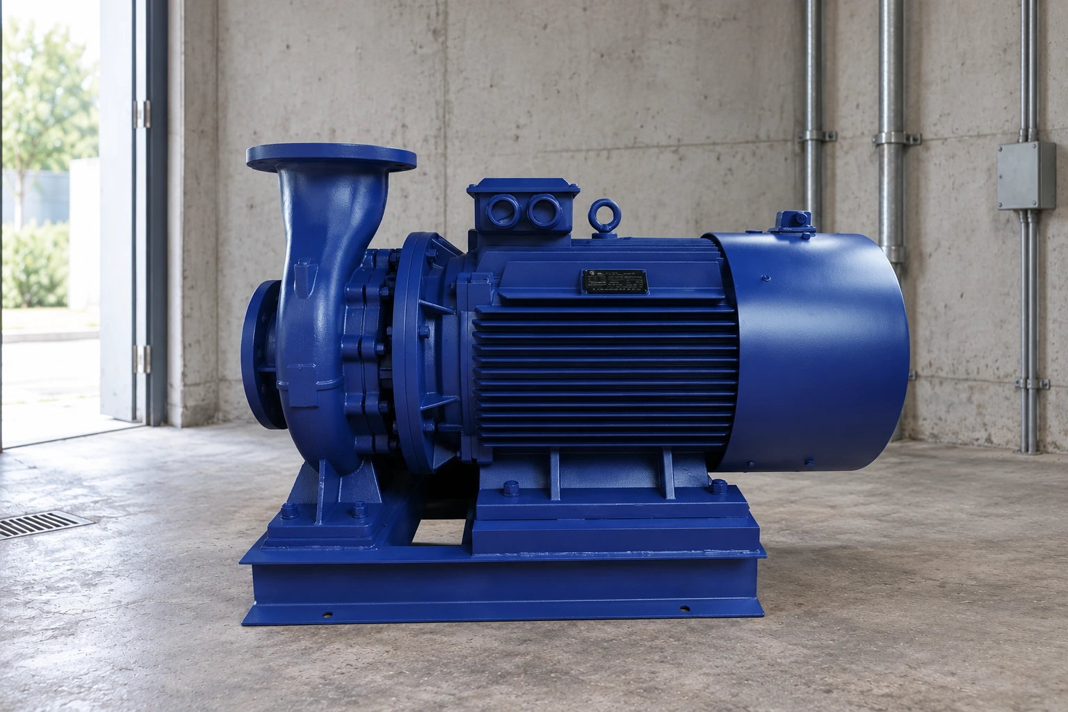
The same caution applies to an inline installation. Our inline pump installation guide explains why support and flange fit must be reviewed in the context of the exact assembly. A procedure for a separately mounted motor cannot be transferred to every inline design.
Complete final alignment and return-to-service verification
Once mounting support is accepted, perform the required shaft alignment, tighten to the approved condition and remeasure. Record cold targets and any specified allowance for operating movement. Refit guards and complete the site’s commissioning checks before starting. Do not run a pump with a loosened mounting arrangement to see whether its vibration improves.
Establish a repeatable operating baseline after authorized return to service. Compare measurements at the same locations and operating condition. Our pump vibration measurement guide explains how to keep that comparison meaningful. A lower vibration reading is useful supporting evidence, but does not replace the mounting and alignment acceptance records.
If the problem returns, compare the new shim stacks, fastener condition, support contact and external attachments against the last accepted record. Investigate the change instead of repeatedly adding material beneath the same foot.
Write a handover record that the next team can use
Include machine identity, drawing revision, inspection date, instrument details, starting condition, measurements at each foot and the final shim arrangement. Attach photographs that identify the mounting locations and the corrected contact surfaces. Record the tightening method, accepted limit source and final alignment result.
State unresolved findings plainly. A support that requires foundation repair should not be described as corrected merely because the machine can be aligned temporarily. Assign the remaining work to an owner and identify whether operation is permitted by the responsible engineer.
Fluke’s pump coupling alignment explanation identifies soft foot among the conditions that affect alignment. For procurement and maintenance planning, request separate evidence for support correction, alignment and operational verification so that a service report does not collapse all three into one unexplained pass.
Formación continua
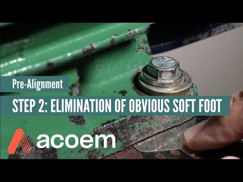
The Acoem pre-alignment lesson below demonstrates obvious soft foot. It is an educational explanation of mounting support, not an acceptance procedure for a particular BORRAPUMP model. Apply only the steps authorized by the equipment documentation and the site’s isolation procedure.
Preguntas frecuentes
Is soft foot the same as shaft misalignment?
No. Soft foot concerns unstable or uneven machine support. Shaft misalignment describes the relationship between shaft axes. A support defect can cause alignment to change during tightening, which is why support should be corrected before final alignment acceptance.
Should I add a shim equal to the displayed movement?
Not automatically. The displayed movement may be measured at a different location from the actual contact gap. Confirm the measurement meaning, support geometry and approved correction method before selecting a shim.
Can tightening the bolts harder fix the problem?
Extra tightening is not an approved substitute for correct support. It may distort the frame or conceal a defect. Use the specified fastener procedure and resolve the contact or external-load problem.
Does every pump use the same soft-foot limit?
No universal value is provided here. Use the applicable equipment instructions and agreed installation criteria. Different machine arrangements and measurement methods require the acceptance basis to be stated clearly.
What should happen after a shim correction?
Repeat the support check, complete final alignment, verify tightening and restore guarding. After authorized startup, record a comparable operating baseline and retain the final shim and alignment records for future maintenance.