
Inspect fire pump alignment at the pump and driver shafts, not by the apparent straightness of the coupling guard. Isolate hazardous energy, record the as-found condition, check soft foot and base integrity, relieve unacceptable pipe strain, and measure angular and offset alignment with appropriate tools. Account for the coupling type and manufacturer tolerances, then recheck after tightening and after the system reaches its operating temperature. Never run the unit with the guard removed. Keep the calculation and acceptance record with the final project documents so future tests use the same basis.
Safety and scope: Fire pumps and their drivers are life-safety equipment. Hydraulic, electrical, diesel, fuel, battery, pressure, rotating-equipment, testing, and impairment work must follow the current approved design, manufacturer instructions, applicable standards, and the authority having jurisdiction. This guide explains the engineering decision path; it does not authorize field changes, bypasses, or operation by unqualified personnel.
Recognize alignment symptoms
Vibration, coupling wear, hot bearings, seal leakage, unusual noise, loose fasteners, or repeated adjustment can indicate alignment or pipe-strain problems but are not proof by themselves. Treat this as a system condition rather than an isolated component choice. Identify the source of every input, the unit used, the operating condition it represents, and the person responsible for approval. If information is preliminary, mark the assumption and test how the decision changes at a conservative boundary. This prevents a neat calculation from hiding an uncertain water level, pressure, valve position, driver condition, or simultaneous demand.
For fire pump alignment, verify this section against the selected pump curve, the actual site arrangement, manufacturer instructions, and the current requirements accepted by the authority having jurisdiction. Check the installed condition as well as the drawing because pipe routes, elevations, supports, controls, and access often change during construction. Record the result in a form that can be repeated during commissioning and later inspection. Do not change a safety-critical setting or isolate fire protection without the approved impairment and restoration process.
Isolate and document
Follow the approved shutdown and impairment process. Record valve and controller status, coupling condition, shims, base, hold-down bolts, and previous readings. The most useful evidence is measured or approved project data, not a copied rule of thumb. Identify the source of every input, the unit used, the operating condition it represents, and the person responsible for approval. If information is preliminary, mark the assumption and test how the decision changes at a conservative boundary. This prevents a neat calculation from hiding an uncertain water level, pressure, valve position, driver condition, or simultaneous demand.
For fire pump alignment, verify this section against the selected pump curve, the actual site arrangement, manufacturer instructions, and the current requirements accepted by the authority having jurisdiction. Check the installed condition as well as the drawing because pipe routes, elevations, supports, controls, and access often change during construction. Record the result in a form that can be repeated during commissioning and later inspection. Do not change a safety-critical setting or isolate fire protection without the approved impairment and restoration process.
Check base and soft foot
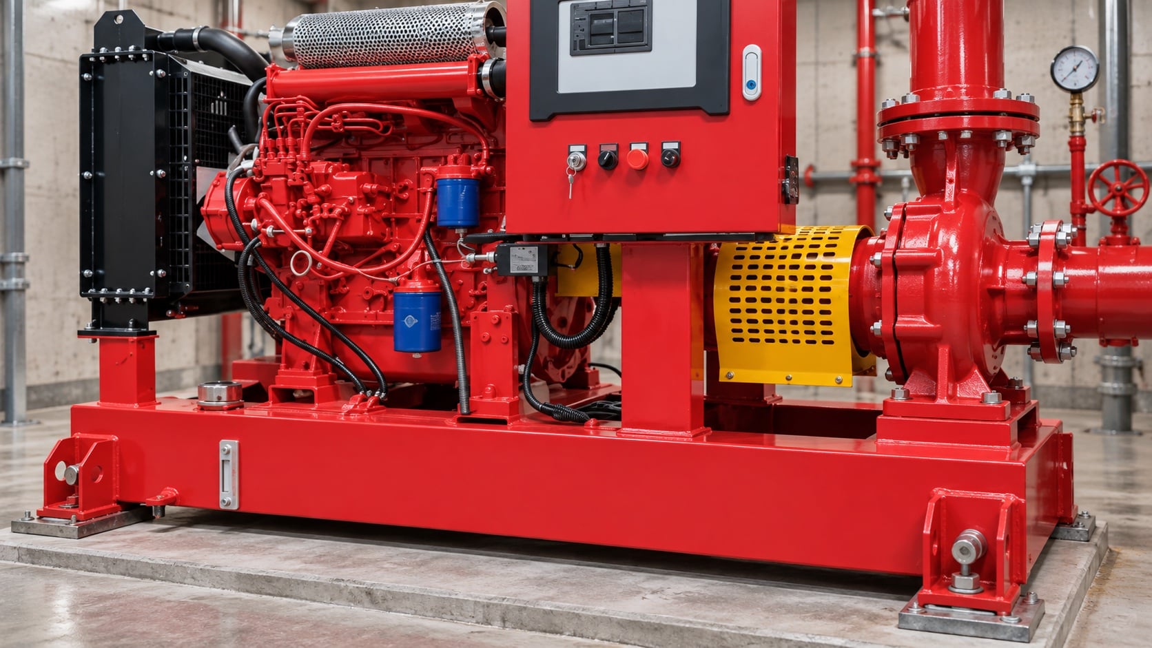
A distorted base, loose grout, corroded supports, or a foot that does not sit flat can move the shafts when bolts are tightened. Review this condition at normal, test, and credible abnormal states before procurement. Identify the source of every input, the unit used, the operating condition it represents, and the person responsible for approval. If information is preliminary, mark the assumption and test how the decision changes at a conservative boundary. This prevents a neat calculation from hiding an uncertain water level, pressure, valve position, driver condition, or simultaneous demand.
For fire pump alignment, verify this section against the selected pump curve, the actual site arrangement, manufacturer instructions, and the current requirements accepted by the authority having jurisdiction. Check the installed condition as well as the drawing because pipe routes, elevations, supports, controls, and access often change during construction. Record the result in a form that can be repeated during commissioning and later inspection. Do not change a safety-critical setting or isolate fire protection without the approved impairment and restoration process.
Measure offset and angular error
Use the method approved for the coupling and accuracy required. Rotate shafts as allowed to distinguish true misalignment from runout or mounting error. The design team should turn this point into a traceable calculation or drawing note. Identify the source of every input, the unit used, the operating condition it represents, and the person responsible for approval. If information is preliminary, mark the assumption and test how the decision changes at a conservative boundary. This prevents a neat calculation from hiding an uncertain water level, pressure, valve position, driver condition, or simultaneous demand.
For fire pump alignment, verify this section against the selected pump curve, the actual site arrangement, manufacturer instructions, and the current requirements accepted by the authority having jurisdiction. Check the installed condition as well as the drawing because pipe routes, elevations, supports, controls, and access often change during construction. Record the result in a form that can be repeated during commissioning and later inspection. Do not change a safety-critical setting or isolate fire protection without the approved impairment and restoration process.
Practical decision table
| Inspection item | What it reveals | Correct response |
|---|---|---|
| Coupling element | Wear, heat, cracking, or contamination | Find cause before replacement |
| Soft foot | Base or foot distortion | Correct support and remeasure |
| Offset alignment | Parallel shaft displacement | Move approved component accurately |
| Angular alignment | Shaft angle difference | Adjust shims or position |
| Pipe strain | External load on pump nozzle | Correct pipe supports and fit |
| Hot verification | Thermal movement and operating behavior | Compare with manufacturer target |
Remove pipe strain
Check whether suction or discharge piping moves the pump when flange bolts are loosened under a safe approved procedure. Correct supports and alignment rather than pulling pipe into place. Treat this as a system condition rather than an isolated component choice. Identify the source of every input, the unit used, the operating condition it represents, and the person responsible for approval. If information is preliminary, mark the assumption and test how the decision changes at a conservative boundary. This prevents a neat calculation from hiding an uncertain water level, pressure, valve position, driver condition, or simultaneous demand.
For fire pump alignment, verify this section against the selected pump curve, the actual site arrangement, manufacturer instructions, and the current requirements accepted by the authority having jurisdiction. Check the installed condition as well as the drawing because pipe routes, elevations, supports, controls, and access often change during construction. Record the result in a form that can be repeated during commissioning and later inspection. Do not change a safety-critical setting or isolate fire protection without the approved impairment and restoration process.
Account for thermal movement
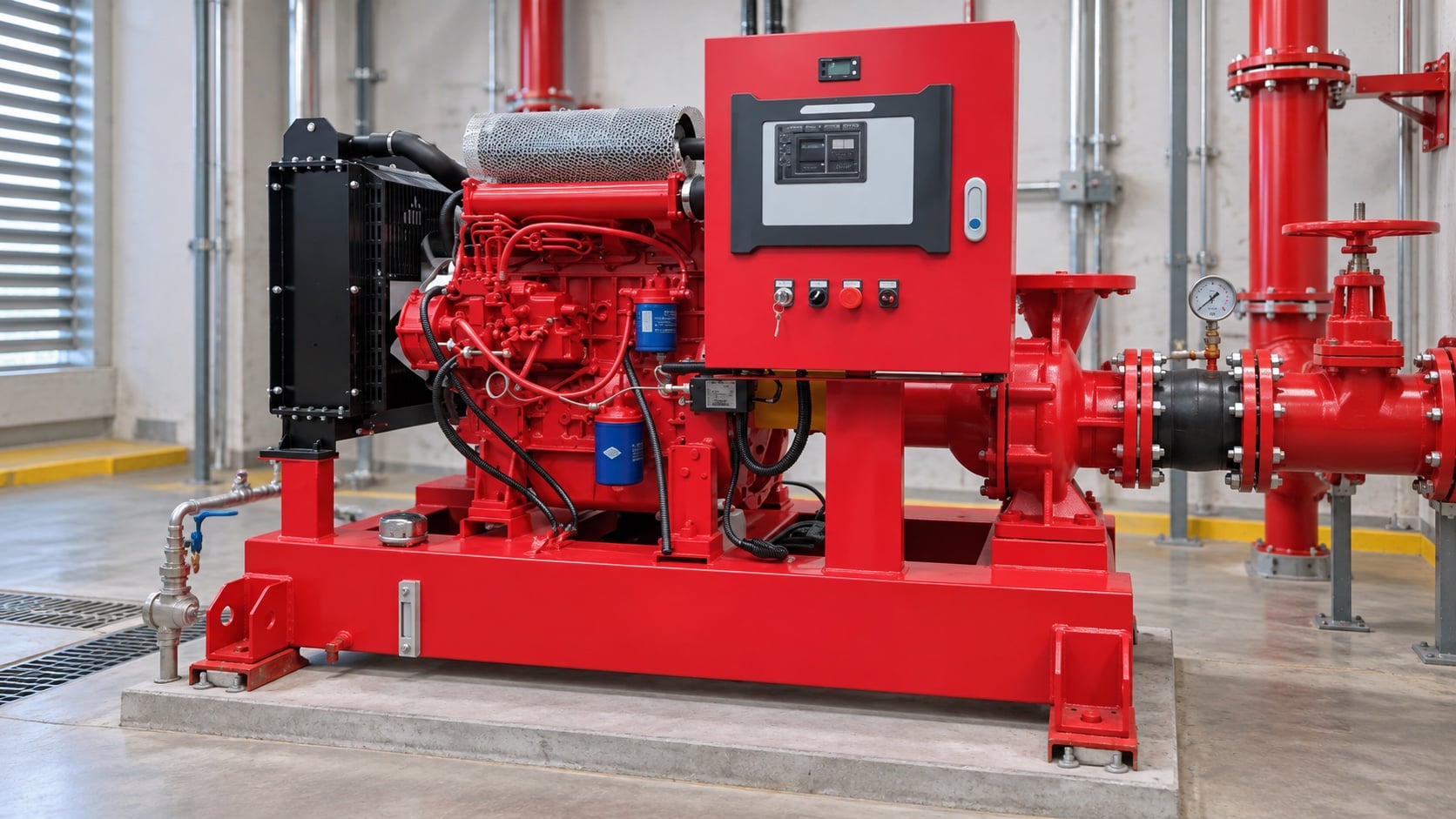
Diesel engines, motors, pumps, and bases can move as temperature changes. Use manufacturer targets where cold alignment must anticipate hot operation. The most useful evidence is measured or approved project data, not a copied rule of thumb. Identify the source of every input, the unit used, the operating condition it represents, and the person responsible for approval. If information is preliminary, mark the assumption and test how the decision changes at a conservative boundary. This prevents a neat calculation from hiding an uncertain water level, pressure, valve position, driver condition, or simultaneous demand.
For fire pump alignment, verify this section against the selected pump curve, the actual site arrangement, manufacturer instructions, and the current requirements accepted by the authority having jurisdiction. Check the installed condition as well as the drawing because pipe routes, elevations, supports, controls, and access often change during construction. Record the result in a form that can be repeated during commissioning and later inspection. Do not change a safety-critical setting or isolate fire protection without the approved impairment and restoration process.
Reassemble and guard
Tighten in a controlled sequence, verify coupling gap where applicable, reinstall the correct guard, and confirm nothing rubs. Review this condition at normal, test, and credible abnormal states before procurement. Identify the source of every input, the unit used, the operating condition it represents, and the person responsible for approval. If information is preliminary, mark the assumption and test how the decision changes at a conservative boundary. This prevents a neat calculation from hiding an uncertain water level, pressure, valve position, driver condition, or simultaneous demand.
For fire pump alignment, verify this section against the selected pump curve, the actual site arrangement, manufacturer instructions, and the current requirements accepted by the authority having jurisdiction. Check the installed condition as well as the drawing because pipe routes, elevations, supports, controls, and access often change during construction. Record the result in a form that can be repeated during commissioning and later inspection. Do not change a safety-critical setting or isolate fire protection without the approved impairment and restoration process.
Verify during operation
Record vibration, bearing temperature, leakage, noise, speed, and performance after startup. Recheck alignment if the base or piping was changed. The design team should turn this point into a traceable calculation or drawing note. Identify the source of every input, the unit used, the operating condition it represents, and the person responsible for approval. If information is preliminary, mark the assumption and test how the decision changes at a conservative boundary. This prevents a neat calculation from hiding an uncertain water level, pressure, valve position, driver condition, or simultaneous demand.
For fire pump alignment, verify this section against the selected pump curve, the actual site arrangement, manufacturer instructions, and the current requirements accepted by the authority having jurisdiction. Check the installed condition as well as the drawing because pipe routes, elevations, supports, controls, and access often change during construction. Record the result in a form that can be repeated during commissioning and later inspection. Do not change a safety-critical setting or isolate fire protection without the approved impairment and restoration process.
How this relates to BORRAPUMP equipment
BORRAPUMP supplies engineered pump equipment for water and fire-protection projects. Review the relevant BORRAPUMP product configuration as a starting point, then submit the required flow, head, water source, driver, power, controls, site conditions, applicable requirements, quantity, and destination. Final selection must use the project hydraulic basis and approved submittal; this guide does not claim that one catalog arrangement fits every jurisdiction or risk.
Related BORRAPUMP guides
Authoritative references
The following sources establish the standards boundary, fire-safety context, and pump-system principles used in this guide. Always apply the edition and local adoption accepted for the project.
- NFPA 25 standard development page
- NFPA 20 standard development page
- U.S. Department of Energy pump systems resources
Educational video
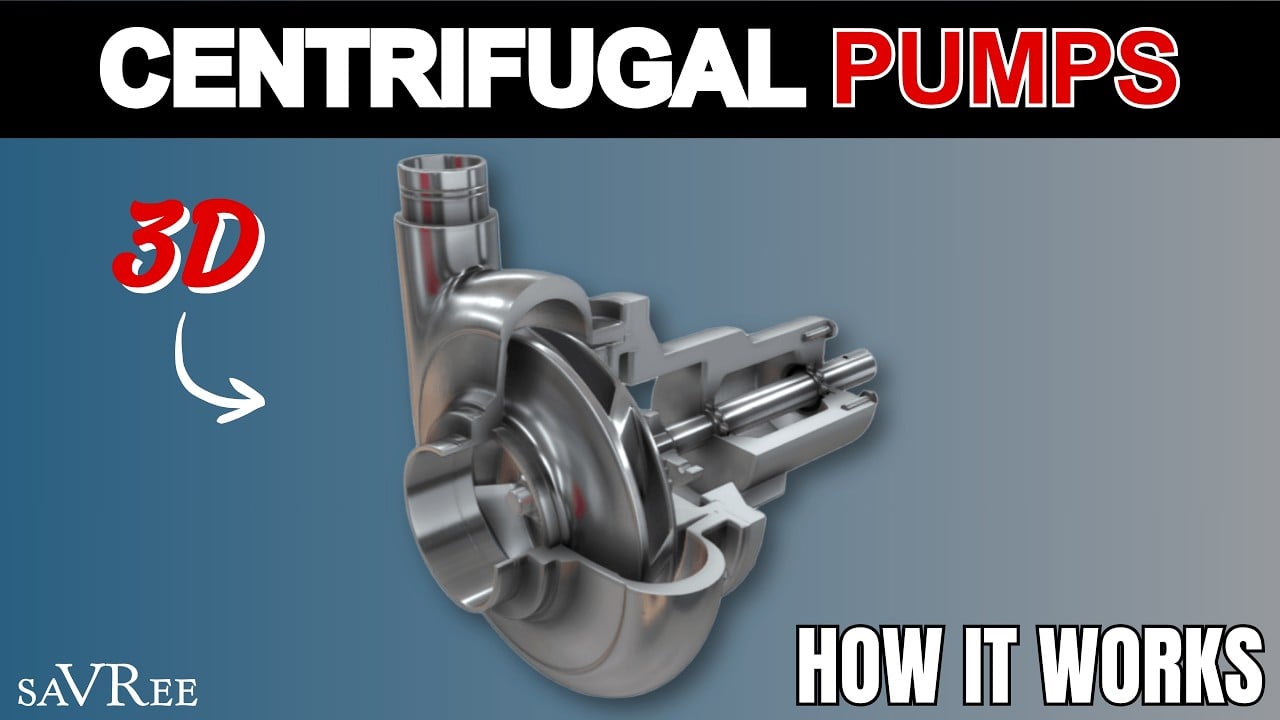
Educational background by saVRee: How Centrifugal Pumps Work. The video supports the underlying engineering concept and does not replace project-specific fire-protection requirements.
Frequently asked questions
Can a flexible coupling tolerate poor alignment?
It accommodates limited movement, but it does not remove the need for alignment within manufacturer limits.
Should pipe bolts pull the flange into place?
No. Piping should be independently supported and aligned without forcing the pump nozzle.
Can alignment be checked with the pump running?
Shaft alignment measurement normally requires safe isolation. Operating checks such as vibration are separate.
Why recheck after tightening?
Bolt loads and soft foot can move the equipment and change the measured result.
Final verification checklist
Before approval, confirm the hydraulic basis, water-source condition, selected pump curve, driver and controller data, component pressure ratings, valve arrangement, test method, access, drainage, alarms, and restoration procedure. Resolve differences between drawings and the installed system. During commissioning, use calibrated instruments and record suction pressure, discharge pressure, flow, speed, driver condition, alarms, and abnormal observations at every required point. Keep the accepted results with the pump-room records so later inspections compare like with like.