
A pump for septic tank service must be selected from the liquid and the chamber duty, not from horsepower alone. First identify whether the pump moves clarified effluent, screened wastewater, or raw sewage containing solids. Then define design flow, total dynamic head, solids size, chamber dimensions, minimum and maximum liquid levels, starts per hour, discharge piping, check valve, alarm, electrical supply, and access for removal. Effluent, sewage, grinder, and ordinary sump pumps are not interchangeable. The final pump and control arrangement must match the septic-system designer's documents, local health requirements, and the manufacturer's published operating limits.
This guide is an early engineering and procurement framework, not a replacement for approved project design, current regulations, manufacturer instructions, or qualified site supervision. Electrical work, energized testing, lifting, confined-space entry, fire-protection work, excavation, hazardous liquids, wastewater, and pressurized systems require task-specific procedures and competent personnel. Preserve automatic protection and system availability while investigating faults. If the actual liquid, duty, site condition, or governing requirement differs from the assumptions, stop and obtain a revised technical review.
Identify what the pump will actually handle
A septic system may place a pump after the primary tank, in a separate dosing chamber, or in a sewage collection basin. Liquid leaving a properly functioning septic tank can still carry suspended solids, grease, fibers, and corrosive gases. A pump moving clarified effluent normally faces a different solids duty from a pump receiving raw sewage. Ask for a process sketch that shows every chamber, screen, baffle, filter, inlet, overflow, and discharge destination. Record the largest expected solids and whether wipes, rags, grit, or fibrous material can enter. Do not choose a grinder pump merely because the word septic appears in the request; grinding changes maintenance, controls, and downstream assumptions. Likewise, a small sump pump intended for clean drainage is not automatically suitable for wastewater. The liquid description should be written into the request for quotation so every supplier evaluates the same service.
Calculate flow and total dynamic head
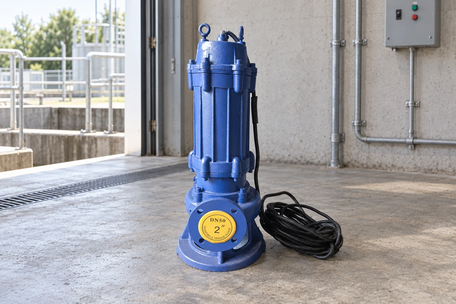
Flow should follow the dosing requirement, inflow pattern, storage volume, and permissible operating cycle. Total dynamic head combines vertical rise from the operating liquid level to the discharge point, required pressure at the destination, and friction through pipe, fittings, check valves, isolation valves, filters, and force mains. Calculate friction at the proposed flow and pipe inside diameter rather than copying a nominal pipe size. Check both the normal start level and the lowest operating level because the static component changes as the chamber is pumped down. Plot the resulting duty point on the certified pump curve and review the whole expected range. A pump that empties the chamber too quickly may cycle excessively; one that is too small may allow the level to rise during peak inflow. The designer should also check emergency storage and the response time after a high-level alarm.
Match solids passage, hydraulics, and motor load
Compare the pump's published solids passage and hydraulic design with the actual waste stream. Vortex, channel, cutter, and grinder arrangements behave differently and should be selected from evidence, not from a generic preference. Review the curve, efficiency, absorbed power, shutoff head, minimum recommended flow, and motor loading at every credible operating point. The discharge pipe and check valve must not create a passage smaller than the project intends to handle. Confirm whether the motor depends on surrounding liquid for cooling and whether the low-level control preserves the required submergence. Frequent starts can heat the motor and shorten contactor life, so chamber volume and level spacing matter. Where two pumps are required, define duty, assist, standby, alternation, and failure behavior instead of simply listing two identical units.
Project decision table
| Decision input | What to confirm | Selection consequence |
|---|---|---|
| Liquid stage | Effluent, screened wastewater, or raw sewage | Defines hydraulic passage and pump type |
| Design flow | Dose, peak inflow, storage and cycle limits | Sets curve duty and chamber drawdown |
| Total dynamic head | Static lift, pressure and friction | Sets required pump head |
| Solids and fibers | Maximum size and actual waste stream | Sets passage, impeller or grinding need |
| Level spacing | Off, lead, lag and high alarm elevations | Controls submergence and starts per hour |
| Maintenance access | Guide rails, lifting and isolation | Allows removal without tank entry |
Design controls, alarms, and level settings
A workable control sequence normally separates pump-on, pump-off, high-level alarm, and any redundant shutdown or backup level. Floats need enough clearance to move without fouling on cables, pipework, walls, grease, or turbulence. Alternative level sensors also require installation and maintenance provisions. State whether the controller alternates pumps, starts the second pump on high inflow, records runtime and starts, reports overload, or sends a remote alarm. The alarm circuit should remain effective when the normal pump circuit fails, subject to the approved electrical design. Verify phase, voltage, overload protection, cable length, junction location, sealing, grounding, and the suitability of every component for the environment. Never enter a tank or chamber to adjust a control without an approved confined-space procedure and qualified personnel.
Plan piping, access, and safe maintenance
Provide an isolation valve, suitable check valve, union or guide-rail arrangement, lifting chain or rated lifting device, and enough access to remove the pump without entering the chamber. Support discharge piping so the pump does not carry pipe loads. Route cables separately from lifting equipment and protect penetrations against leakage and gas migration as required by the design. The cover must control unauthorized access while allowing inspection and removal. Locate the chamber where service vehicles and technicians can work without traffic, fall, or electrical hazards. Ventilation, gas testing, fall protection, lockout, sanitation, and confined-space controls are site responsibilities. A supplier drawing should show chamber diameter, rail position, discharge connection, valves, level devices, cable route, and minimum removal clearance before concrete or piping is finalized.
Commission the pump as a complete system
Before commissioning, remove construction debris, verify free movement of level devices, inspect valves and piping, test insulation and continuity using approved procedures, confirm rotation where applicable, and check the controller logic without bypassing protection. Run clean-water or approved functional tests when the project procedure allows, then observe actual operation at representative levels. Record start and stop elevations, drawdown time, estimated flow, discharge pressure where available, motor current, voltage, alarm operation, pump alternation, check-valve closure, leaks, vibration, and abnormal noise. Confirm that the downstream system accepts the discharge. Establish a baseline of runtime and starts so future changes reveal infiltration, blockage, wear, or control drift. Commissioning is incomplete if the pump runs but the high-level alarm, standby sequence, or safe removal arrangement has not been demonstrated.
Supplier comparison and acceptance record
A complete supplier comparison should use one common data sheet. Put the design and alternate duty points, liquid, temperature, solids, site elevation, power, controls, installation, operating hours, quantity, destination, and required documents at the top. Normalize differences in scope before comparing price or efficiency. Request a certified curve or capacity data, absorbed power, operating limits, materials, dimensions, weight, connections, motor or driver, controller, accessories, tests, preservation, spare parts, installation instructions, and warranty boundary. Record every deviation and unresolved assumption. During technical review, trace each offered feature back to a project input instead of awarding points for features that the duty does not need. During commissioning, measure the same variables used for selection so the installed result can be compared with the original basis. If field conditions differ, update the calculation and obtain responsible approval before changing equipment or protection settings.
System integration and lifecycle planning
Treat the pump as one component of a complete hydraulic and control system. Review the source, intake, suction or inlet arrangement, pump, driver, discharge piping, valves, instruments, controls, power, drainage, foundation, lifting route, and receiving system on the same drawing. Confirm normal operation, minimum and maximum demand, startup, shutdown, blocked or closed paths, loss of power, standby changeover, alarm response, cleaning, and maintenance isolation. Interfaces create many failures: a correctly selected pump can still underperform because the available supply differs from the assumed level, a pipe is smaller than scheduled, a valve has an unexpected pressure loss, a controller uses the wrong sensor location, or maintenance access was removed during civil design. Resolve interface ownership before purchase. The pump vendor cannot approve the building, well, wastewater process, fire-protection system, environmental discharge, or electrical installation unless that responsibility is explicitly included and supported by qualified review.
Lifecycle planning should begin before shipment and continue through every documented operating change. Identify the expected operating hours, starts, standby periods, storage conditions, inspection route, removal method, lifting capacity, cleaning requirement, consumables, critical spares, service tools, and data that operators will trend. Establish baseline readings during acceptance and keep them with the curve, data sheet, drawings, controller settings, certificates, manuals, and parts list. A future technician should be able to tell what duty was approved, what was measured at startup, and what changed. When performance deteriorates, compare evidence before replacing equipment. Flow, pressure, level, current, power, vibration, temperature, runtime, starts, alarms, and liquid condition often separate hydraulic, mechanical, electrical, and process causes. This record reduces unnecessary replacement and supports a safer decision when operating conditions no longer match the original selection.
How this topic connects to BORRAPUMP equipment
This guide supports early review of the pump for septic tank application route. It does not assign a final model or claim that one standard configuration fits every project. Send the duty points, liquid data, site drawing, power supply, controls, quantity, destination, required approvals, and inspection scope so the proposed product can be checked against the real service.
Related BORRAPUMP engineering guides
Authoritative sources and further learning
U.S. EPA septic systems; OSHA permit-required confined spaces; OSHA electrical safety-related work practices. These sources provide general safety, environmental, or engineering context. The current adopted rules, project approvals, and equipment instructions remain controlling.

Educational video by Practical Engineering: Do Pumps Create Pressure or Flow?. It explains background principles and does not replace project-specific instructions.
Frequently asked questions
Can a sump pump be used in a septic tank?
Only if its manufacturer and the system designer approve it for the actual liquid, solids, head, duty cycle, environment, and controls. A clean-water sump pump is not automatically a sewage or effluent pump.
What size septic pump do I need?
Size from required flow, total dynamic head, solids duty, chamber volume, cycle limits, and the certified pump curve. Horsepower alone is not a sizing method.
Is a grinder pump always better?
No. A grinder is useful only where the approved system requires size reduction. It adds different maintenance and downstream considerations.
Why does the high-level alarm need separate attention?
The alarm must warn of a rising level when normal pumping is unavailable. Its power, sensor, notification path, and test procedure should be defined and verified.
Final project checkpoint
Before order placement or field change, reconcile the approved duty and drawings with the supplier data, materials, dimensions, weights, connections, driver, controls, accessories, protection, test scope, documentation, spare parts, installation method, maintenance access, and destination requirements. Record remaining assumptions and assign responsibility for closing them. The final accepted information should be the same basis used for installation, commissioning, and future maintenance.