
Calculate fire pump flow and pressure from the approved fire-protection hydraulic demand, the available water-supply curve, elevation, pipe friction, and the residual pressure required at the controlling point. Do not select the pump by floor area, pipe diameter, or a guessed pressure alone. The required duty point must sit on a documented pump curve and the complete system must be checked at no-flow, rated-flow, and higher-flow conditions required by the governing project criteria. Keep the calculation and acceptance record with the final project documents so future tests use the same basis.
Keamanan dan cakupan: Pompa pemadam kebakaran dan penggeraknya adalah peralatan keselamatan jiwa. Pekerjaan hidrolik, kelistrikan, diesel, bahan bakar, baterai, tekanan, peralatan berputar, pengujian, dan gangguan harus mengikuti desain disetujui saat ini, instruksi pabrikan, standar yang berlaku, dan otoritas yang memiliki yurisdiksi. Panduan ini menjelaskan jalur keputusan teknik; panduan ini tidak mengizinkan perubahan lapangan, pengoperasian bypass, atau pengoperasian oleh personel yang не berkualifikasi.
- Start with the approved system demand
- Separate source pressure from pump pressure
- Calculate total dynamic head
- Convert pressure and head correctly
- Check the full pump curve
- Coordinate zoning and pressure control
- Build a calculation package
- Validate at acceptance testing
- Tabel keputusan
- Pertanyaan yang sering diajukan
Start with the approved system demand
Use the hydraulic calculation for the most demanding sprinkler, standpipe, hydrant, foam, or combined scenario. Record flow, residual pressure, hose demand, duration, and which simultaneous systems are included. Treat this as a system condition rather than an isolated component choice. Identify the source of every input, the unit used, the operating condition it represents, and the person responsible for approval. If information is preliminary, mark the assumption and test how the decision changes at a conservative boundary. This prevents a neat calculation from hiding an uncertain water level, pressure, valve position, driver condition, or simultaneous demand.
For fire pump flow calculation, verify this section against the selected pump curve, the actual site arrangement, manufacturer instructions, and the current requirements accepted by the authority having jurisdiction. Check the installed condition as well as the drawing because pipe routes, elevations, supports, controls, and access often change during construction. Record the result in a form that can be repeated during commissioning and later inspection. Do not change a safety-critical setting or isolate fire protection without the approved impairment and restoration process.
Separate source pressure from pump pressure
Plot the reliable water-supply curve at the pump suction. Use the conservative available pressure at the selected flow and account for tank level, municipal variation, and suction-side losses. The most useful evidence is measured or approved project data, not a copied rule of thumb. Identify the source of every input, the unit used, the operating condition it represents, and the person responsible for approval. If information is preliminary, mark the assumption and test how the decision changes at a conservative boundary. This prevents a neat calculation from hiding an uncertain water level, pressure, valve position, driver condition, or simultaneous demand.
For fire pump flow calculation, verify this section against the selected pump curve, the actual site arrangement, manufacturer instructions, and the current requirements accepted by the authority having jurisdiction. Check the installed condition as well as the drawing because pipe routes, elevations, supports, controls, and access often change during construction. Record the result in a form that can be repeated during commissioning and later inspection. Do not change a safety-critical setting or isolate fire protection without the approved impairment and restoration process.
Calculate total dynamic head
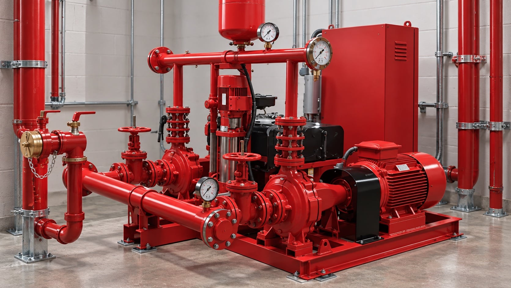
Add static elevation, friction through pipe and fittings, equipment losses, and required residual head, then subtract dependable suction head. Keep all terms in one consistent unit system. Review this condition at normal, test, and credible abnormal states before procurement. Identify the source of every input, the unit used, the operating condition it represents, and the person responsible for approval. If information is preliminary, mark the assumption and test how the decision changes at a conservative boundary. This prevents a neat calculation from hiding an uncertain water level, pressure, valve position, driver condition, or simultaneous demand.
For fire pump flow calculation, verify this section against the selected pump curve, the actual site arrangement, manufacturer instructions, and the current requirements accepted by the authority having jurisdiction. Check the installed condition as well as the drawing because pipe routes, elevations, supports, controls, and access often change during construction. Record the result in a form that can be repeated during commissioning and later inspection. Do not change a safety-critical setting or isolate fire protection without the approved impairment and restoration process.
Convert pressure and head correctly
For water, pressure and head are related through density and gravity. For other permitted liquids or unusual temperature, use actual density rather than a water shortcut. The design team should turn this point into a traceable calculation or drawing note. Identify the source of every input, the unit used, the operating condition it represents, and the person responsible for approval. If information is preliminary, mark the assumption and test how the decision changes at a conservative boundary. This prevents a neat calculation from hiding an uncertain water level, pressure, valve position, driver condition, or simultaneous demand.
For fire pump flow calculation, verify this section against the selected pump curve, the actual site arrangement, manufacturer instructions, and the current requirements accepted by the authority having jurisdiction. Check the installed condition as well as the drawing because pipe routes, elevations, supports, controls, and access often change during construction. Record the result in a form that can be repeated during commissioning and later inspection. Do not change a safety-critical setting or isolate fire protection without the approved impairment and restoration process.
Tabel keputusan praktis
| Masukan | Mengapa itu penting | Bukti yang diperlukan |
|---|---|---|
| System demand | Defines the target flow and residual pressure | Perhitungan hidrolik disetujui |
| Pasokan air | Determines available suction pressure | Current flow test or tank data |
| Elevation | Creates static head | Verified elevations |
| Pipe and fittings | Create flow-dependent losses | As-built sizes and route |
| Kurva pompa | Confirms feasible duty | Manufacturer certified curve |
| Driver and power | Must carry the required load | Driver and controller data |
Check the full pump curve
Verify shutoff pressure, the rated duty point, higher-flow performance, driver loading, suction conditions, and downstream pressure limits. One point on a curve is not enough. Treat this as a system condition rather than an isolated component choice. Identify the source of every input, the unit used, the operating condition it represents, and the person responsible for approval. If information is preliminary, mark the assumption and test how the decision changes at a conservative boundary. This prevents a neat calculation from hiding an uncertain water level, pressure, valve position, driver condition, or simultaneous demand.
For fire pump flow calculation, verify this section against the selected pump curve, the actual site arrangement, manufacturer instructions, and the current requirements accepted by the authority having jurisdiction. Check the installed condition as well as the drawing because pipe routes, elevations, supports, controls, and access often change during construction. Record the result in a form that can be repeated during commissioning and later inspection. Do not change a safety-critical setting or isolate fire protection without the approved impairment and restoration process.
Coordinate zoning and pressure control
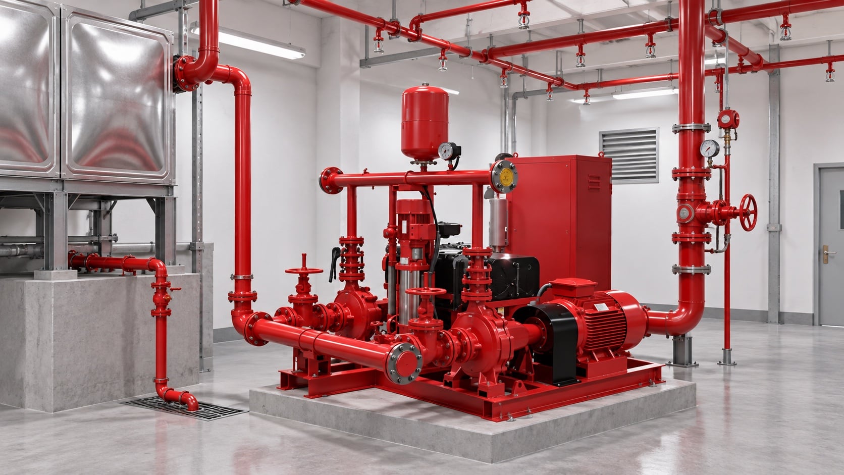
High-rise or multi-zone systems may need separate pumps, tanks, pressure-regulating devices, or staged arrangements. Do not use a relief valve as routine operating pressure control. The most useful evidence is measured or approved project data, not a copied rule of thumb. Identify the source of every input, the unit used, the operating condition it represents, and the person responsible for approval. If information is preliminary, mark the assumption and test how the decision changes at a conservative boundary. This prevents a neat calculation from hiding an uncertain water level, pressure, valve position, driver condition, or simultaneous demand.
For fire pump flow calculation, verify this section against the selected pump curve, the actual site arrangement, manufacturer instructions, and the current requirements accepted by the authority having jurisdiction. Check the installed condition as well as the drawing because pipe routes, elevations, supports, controls, and access often change during construction. Record the result in a form that can be repeated during commissioning and later inspection. Do not change a safety-critical setting or isolate fire protection without the approved impairment and restoration process.
Build a calculation package
Include demand calculations, source test, pipe model, pump curve, driver data, control sequence, valve schedule, and assumptions so another reviewer can reproduce the result. Review this condition at normal, test, and credible abnormal states before procurement. Identify the source of every input, the unit used, the operating condition it represents, and the person responsible for approval. If information is preliminary, mark the assumption and test how the decision changes at a conservative boundary. This prevents a neat calculation from hiding an uncertain water level, pressure, valve position, driver condition, or simultaneous demand.
For fire pump flow calculation, verify this section against the selected pump curve, the actual site arrangement, manufacturer instructions, and the current requirements accepted by the authority having jurisdiction. Check the installed condition as well as the drawing because pipe routes, elevations, supports, controls, and access often change during construction. Record the result in a form that can be repeated during commissioning and later inspection. Do not change a safety-critical setting or isolate fire protection without the approved impairment and restoration process.
Validate at acceptance testing
Measure suction and discharge pressure and test flow using calibrated instruments. Compare corrected results with the accepted curve and investigate any material deviation before handover. The design team should turn this point into a traceable calculation or drawing note. Identify the source of every input, the unit used, the operating condition it represents, and the person responsible for approval. If information is preliminary, mark the assumption and test how the decision changes at a conservative boundary. This prevents a neat calculation from hiding an uncertain water level, pressure, valve position, driver condition, or simultaneous demand.
For fire pump flow calculation, verify this section against the selected pump curve, the actual site arrangement, manufacturer instructions, and the current requirements accepted by the authority having jurisdiction. Check the installed condition as well as the drawing because pipe routes, elevations, supports, controls, and access often change during construction. Record the result in a form that can be repeated during commissioning and later inspection. Do not change a safety-critical setting or isolate fire protection without the approved impairment and restoration process.
Bagaimana ini terkait dengan peralatan BORRAPUMP
BORRAPUMP memasok peralatan pompa rekayasa untuk proyek-proyek air dan proteksi kebakaran. Tinjau yang relevan Konfigurasi produk BORRAPUMP sebagai titik awal, lalu serahkan aliran, tinggi tekan, sumber air, penggerak, daya, kontrol, kondisi lokasi, persyaratan yang berlaku, jumlah, dan tujuan yang diperlukan. Pemilihan akhir harus menggunakan dasar hidrolik proyek dan submittal yang disetujui; panduan ini tidak mengklaim bahwa satu susunan katalog cocok untuk setiap yurisdiksi atau risiko.
Panduan BORRAPUMP terkait
- Dasar-dasar desain sistem pompa pemadam kebakaran
- pemilihan pompa pemadam kebakaran
- pompa pemadam kebakaran diesel versus elektrik
Referensi otoritatif
Sumber-sumber berikut menetapkan batas standar, konteks keselamatan kebakaran, dan prinsip sistem pompa yang digunakan dalam panduan ini. Selalu terapkan edisi dan adopsi lokal yang disetujui untuk proyek tersebut.
- Halaman pengembangan standar NFPA 20
- Sumber daya sistem pompa Departemen Energi AS
- penelitian perlindungan kebakaran NIST
Video edukasi

Latar belakang pendidikan oleh Practical Engineering: Apakah Pompa Menghasilkan Tekanan atau Aliran?. Video tersebut mendukung konsep teknik yang mendasar dan tidak menggantikan persyaratan perlindungan kebakaran khusus proyek.
Pertanyaan yang sering diajukan
Can I size a fire pump from building area?
No. Building area may influence the protection design, but the pump duty comes from the approved hydraulic demand and water supply.
Should I add suction and discharge gauge readings?
Use differential pressure across the pump, then convert it correctly to head and include elevation differences between gauge points where relevant.
What if several systems operate together?
Use the combination required by the approved design basis and authority having jurisdiction. Do not assume every demand is simultaneous or independent.
Can a larger pump provide extra safety?
Oversizing can create excessive pressure, unstable operation, and difficult testing. Select against the complete system curve and permitted pressure limits.
Daftar periksa verifikasi akhir
Sebelum persetujuan, konfirmasikan basis hidrolik, kondisi sumber air, kurva pompa yang dipilih, data penggerak dan pengontrol, peringkat tekanan komponen, susunan katup, metode pengujian, akses, drainase, alarm, dan prosedur pemulihan. Selesaikan perbedaan antara gambar kerja dan sistem yang terpasang. Selama pengujian (commissioning), gunakan instrumen yang dikalibrasi dan catat tekanan isap, tekanan buang, aliran, kecepatan, kondisi penggerak, alarm, dan pengamatan tidak normal pada setiap titik yang diperlukan. Simpan hasil yang diterima bersama catatan ruang pompa sehingga pemeriksaan selanjutnya dapat membandingkan hal yang setara.