
Calculate fire pump flow and pressure from the approved fire-protection hydraulic demand, the available water-supply curve, elevation, pipe friction, and the residual pressure required at the controlling point. Do not select the pump by floor area, pipe diameter, or a guessed pressure alone. The required duty point must sit on a documented pump curve and the complete system must be checked at no-flow, rated-flow, and higher-flow conditions required by the governing project criteria. Keep the calculation and acceptance record with the final project documents so future tests use the same basis.
Segurança e âmbito: As bombas de incêndio e respetivos acionadores são equipamento de segurança de vida. Os trabalhos hidráulicos, elétricos, a diesel, de combustível, de bateria, de pressão, de equipamento rotativo, de ensaio e de anomalias devem seguir o projeto aprovado em vigor, as instruções do fabricante, as normas aplicáveis e a autoridade com jurisdição. Este guia explica o caminho de decisão de engenharia; não autoriza alterações em campo, desvios ou a operação por pessoal não qualificado.
- Start with the approved system demand
- Separate source pressure from pump pressure
- Calculate total dynamic head
- Convert pressure and head correctly
- Check the full pump curve
- Coordinate zoning and pressure control
- Build a calculation package
- Validate at acceptance testing
- tabela de decisão
- Perguntas frequentes
Start with the approved system demand
Use the hydraulic calculation for the most demanding sprinkler, standpipe, hydrant, foam, or combined scenario. Record flow, residual pressure, hose demand, duration, and which simultaneous systems are included. Treat this as a system condition rather than an isolated component choice. Identify the source of every input, the unit used, the operating condition it represents, and the person responsible for approval. If information is preliminary, mark the assumption and test how the decision changes at a conservative boundary. This prevents a neat calculation from hiding an uncertain water level, pressure, valve position, driver condition, or simultaneous demand.
For fire pump flow calculation, verify this section against the selected pump curve, the actual site arrangement, manufacturer instructions, and the current requirements accepted by the authority having jurisdiction. Check the installed condition as well as the drawing because pipe routes, elevations, supports, controls, and access often change during construction. Record the result in a form that can be repeated during commissioning and later inspection. Do not change a safety-critical setting or isolate fire protection without the approved impairment and restoration process.
Separate source pressure from pump pressure
Plot the reliable water-supply curve at the pump suction. Use the conservative available pressure at the selected flow and account for tank level, municipal variation, and suction-side losses. The most useful evidence is measured or approved project data, not a copied rule of thumb. Identify the source of every input, the unit used, the operating condition it represents, and the person responsible for approval. If information is preliminary, mark the assumption and test how the decision changes at a conservative boundary. This prevents a neat calculation from hiding an uncertain water level, pressure, valve position, driver condition, or simultaneous demand.
For fire pump flow calculation, verify this section against the selected pump curve, the actual site arrangement, manufacturer instructions, and the current requirements accepted by the authority having jurisdiction. Check the installed condition as well as the drawing because pipe routes, elevations, supports, controls, and access often change during construction. Record the result in a form that can be repeated during commissioning and later inspection. Do not change a safety-critical setting or isolate fire protection without the approved impairment and restoration process.
Calculate total dynamic head
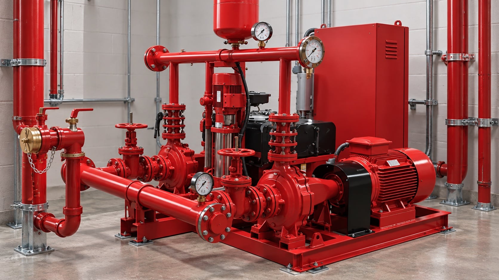
Add static elevation, friction through pipe and fittings, equipment losses, and required residual head, then subtract dependable suction head. Keep all terms in one consistent unit system. Review this condition at normal, test, and credible abnormal states before procurement. Identify the source of every input, the unit used, the operating condition it represents, and the person responsible for approval. If information is preliminary, mark the assumption and test how the decision changes at a conservative boundary. This prevents a neat calculation from hiding an uncertain water level, pressure, valve position, driver condition, or simultaneous demand.
For fire pump flow calculation, verify this section against the selected pump curve, the actual site arrangement, manufacturer instructions, and the current requirements accepted by the authority having jurisdiction. Check the installed condition as well as the drawing because pipe routes, elevations, supports, controls, and access often change during construction. Record the result in a form that can be repeated during commissioning and later inspection. Do not change a safety-critical setting or isolate fire protection without the approved impairment and restoration process.
Convert pressure and head correctly
For water, pressure and head are related through density and gravity. For other permitted liquids or unusual temperature, use actual density rather than a water shortcut. The design team should turn this point into a traceable calculation or drawing note. Identify the source of every input, the unit used, the operating condition it represents, and the person responsible for approval. If information is preliminary, mark the assumption and test how the decision changes at a conservative boundary. This prevents a neat calculation from hiding an uncertain water level, pressure, valve position, driver condition, or simultaneous demand.
For fire pump flow calculation, verify this section against the selected pump curve, the actual site arrangement, manufacturer instructions, and the current requirements accepted by the authority having jurisdiction. Check the installed condition as well as the drawing because pipe routes, elevations, supports, controls, and access often change during construction. Record the result in a form that can be repeated during commissioning and later inspection. Do not change a safety-critical setting or isolate fire protection without the approved impairment and restoration process.
Tabela de decisão prática
| Entrada | Porque é que isso importa | Evidência necessária |
|---|---|---|
| System demand | Defines the target flow and residual pressure | Cálculo hidráulico aprovado |
| Abastecimento de água | Determines available suction pressure | Current flow test or tank data |
| Elevation | Creates static head | Verified elevations |
| Pipe and fittings | Create flow-dependent losses | As-built sizes and route |
| curva da bomba | Confirms feasible duty | Manufacturer certified curve |
| Driver and power | Must carry the required load | Driver and controller data |
Check the full pump curve
Verify shutoff pressure, the rated duty point, higher-flow performance, driver loading, suction conditions, and downstream pressure limits. One point on a curve is not enough. Treat this as a system condition rather than an isolated component choice. Identify the source of every input, the unit used, the operating condition it represents, and the person responsible for approval. If information is preliminary, mark the assumption and test how the decision changes at a conservative boundary. This prevents a neat calculation from hiding an uncertain water level, pressure, valve position, driver condition, or simultaneous demand.
For fire pump flow calculation, verify this section against the selected pump curve, the actual site arrangement, manufacturer instructions, and the current requirements accepted by the authority having jurisdiction. Check the installed condition as well as the drawing because pipe routes, elevations, supports, controls, and access often change during construction. Record the result in a form that can be repeated during commissioning and later inspection. Do not change a safety-critical setting or isolate fire protection without the approved impairment and restoration process.
Coordinate zoning and pressure control
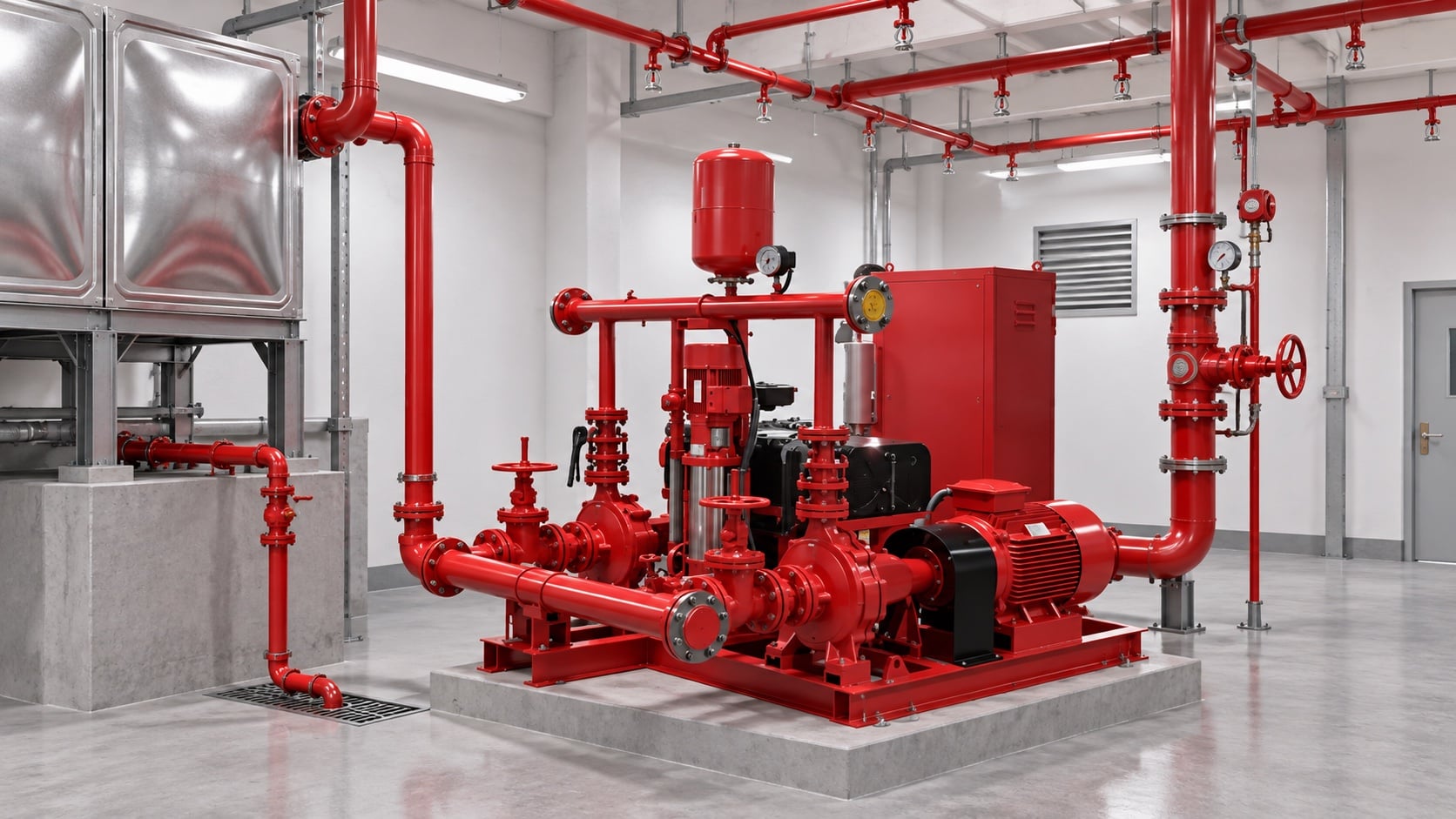
High-rise or multi-zone systems may need separate pumps, tanks, pressure-regulating devices, or staged arrangements. Do not use a relief valve as routine operating pressure control. The most useful evidence is measured or approved project data, not a copied rule of thumb. Identify the source of every input, the unit used, the operating condition it represents, and the person responsible for approval. If information is preliminary, mark the assumption and test how the decision changes at a conservative boundary. This prevents a neat calculation from hiding an uncertain water level, pressure, valve position, driver condition, or simultaneous demand.
For fire pump flow calculation, verify this section against the selected pump curve, the actual site arrangement, manufacturer instructions, and the current requirements accepted by the authority having jurisdiction. Check the installed condition as well as the drawing because pipe routes, elevations, supports, controls, and access often change during construction. Record the result in a form that can be repeated during commissioning and later inspection. Do not change a safety-critical setting or isolate fire protection without the approved impairment and restoration process.
Build a calculation package
Include demand calculations, source test, pipe model, pump curve, driver data, control sequence, valve schedule, and assumptions so another reviewer can reproduce the result. Review this condition at normal, test, and credible abnormal states before procurement. Identify the source of every input, the unit used, the operating condition it represents, and the person responsible for approval. If information is preliminary, mark the assumption and test how the decision changes at a conservative boundary. This prevents a neat calculation from hiding an uncertain water level, pressure, valve position, driver condition, or simultaneous demand.
For fire pump flow calculation, verify this section against the selected pump curve, the actual site arrangement, manufacturer instructions, and the current requirements accepted by the authority having jurisdiction. Check the installed condition as well as the drawing because pipe routes, elevations, supports, controls, and access often change during construction. Record the result in a form that can be repeated during commissioning and later inspection. Do not change a safety-critical setting or isolate fire protection without the approved impairment and restoration process.
Validate at acceptance testing
Measure suction and discharge pressure and test flow using calibrated instruments. Compare corrected results with the accepted curve and investigate any material deviation before handover. The design team should turn this point into a traceable calculation or drawing note. Identify the source of every input, the unit used, the operating condition it represents, and the person responsible for approval. If information is preliminary, mark the assumption and test how the decision changes at a conservative boundary. This prevents a neat calculation from hiding an uncertain water level, pressure, valve position, driver condition, or simultaneous demand.
For fire pump flow calculation, verify this section against the selected pump curve, the actual site arrangement, manufacturer instructions, and the current requirements accepted by the authority having jurisdiction. Check the installed condition as well as the drawing because pipe routes, elevations, supports, controls, and access often change during construction. Record the result in a form that can be repeated during commissioning and later inspection. Do not change a safety-critical setting or isolate fire protection without the approved impairment and restoration process.
Como isto se relaciona com o equipamento BORRAPUMP
A BORRAPUMP fornece equipamento de bombagem concebido por engenharia para projetos de água e proteção contra incêndios. Reveja o relevante Configuração do produto BORRAPUMP como ponto de partida, submeta seguidamente o caudal, a altura manométria, a fonte de água, o acionador, a potência, os controlos, as condições do local, os requisitos aplicáveis, a quantidade e o destino. A seleção final deve utilizar a base hidráulica do projeto e a submissão aprovada; este guia não afirma que uma disposição de catálogo se adapta a todas as jurisdições ou riscos.
Guias BORRAPUMP relacionados
- noções básicas de conceção de sistemas de bombagem de incêndio
- seleção de bombas de combate a incêndio
- bombas de incêndio a gasóleo versus elétricas
Referências fidedignas
As fontes seguintes estabelecem os limites normativos, o contexto de segurança contra incêndios e os princípios dos sistemas de bombagem utilizados neste guia. Aplique sempre a edição e a adoção local aceites para o projeto.
- Página de desenvolvimento da norma NFPA 20
- Recursos de sistemas de bombagem do Departamento de Energia dos EUA
- investigação sobre protecção contra incêndios do NIST
Vídeo educativo

Formação académica por Practical Engineering: As bombas criam pressão ou caudal?. O vídeo apoia o conceito de engenharia subjacente e não substitui os requisitos de proteção contra incêndio específicos do projeto.
Perguntas frequentes
Can I size a fire pump from building area?
No. Building area may influence the protection design, but the pump duty comes from the approved hydraulic demand and water supply.
Should I add suction and discharge gauge readings?
Use differential pressure across the pump, then convert it correctly to head and include elevation differences between gauge points where relevant.
What if several systems operate together?
Use the combination required by the approved design basis and authority having jurisdiction. Do not assume every demand is simultaneous or independent.
Can a larger pump provide extra safety?
Oversizing can create excessive pressure, unstable operation, and difficult testing. Select against the complete system curve and permitted pressure limits.
Lista de verificação de verificação final
Antes da aprovação, confirme a base hidráulica, a condição da captação de água, a curva da bomba selecionada, os dados do acionador e do controlador, as pressões nominais dos componentes, o arranjo das válvulas, o método de ensaio, o acesso, a drenagem, os alarmes e o procedimento de restabelecimento. Resolva as divergências entre os desenhos e o sistema instalado. Durante a comissão, utilize instrumentos calibrados e registe a pressão de aspiração, a pressão de descarga, o caudal, a velocidade, a condição do acionador, os alarmes e as observações anómalas em cada ponto necessário. Mantenha os resultados aceites junto dos registos da casa de bombas para que inspeções posteriores comparem dados equivalentes.