
Calculate fire pump flow and pressure from the approved fire-protection hydraulic demand, the available water-supply curve, elevation, pipe friction, and the residual pressure required at the controlling point. Do not select the pump by floor area, pipe diameter, or a guessed pressure alone. The required duty point must sit on a documented pump curve and the complete system must be checked at no-flow, rated-flow, and higher-flow conditions required by the governing project criteria. Keep the calculation and acceptance record with the final project documents so future tests use the same basis.
ความปลอดภัยและขอบเขต: ปั๊มดับเพลิงและชุดขับเคลื่อนเป็นอุปกรณ์เพื่อความปลอดภัยในชีวิต งานระบบไฮดรอลิก ระบบไฟฟ้า ดีเซล เชื้อเพลิง แบตเตอรี่ ความดัน อุปกรณ์หมุน การทดสอบ และการจัดการข้อบกพร่อง จะต้องเป็นไปตามการออกแบบที่ได้รับอนุมัติในปัจจุบัน คำแนะนำของผู้ผลิต มาตรฐานที่เกี่ยวข้อง และหน่วยงานที่มีเขตอำนาจ คู่มือนี้อธิบายถึงเส้นทางการตัดสินใจทางวิศวกรรม โดยไม่ได้ให้สิทธิ์ในการเปลี่ยนแปลงหน้างาน การบายพาส หรือการปฏิบัติงานโดยบุคลากรที่ไม่มีคุณสมบัติ.
- Start with the approved system demand
- Separate source pressure from pump pressure
- Calculate total dynamic head
- Convert pressure and head correctly
- Check the full pump curve
- Coordinate zoning and pressure control
- Build a calculation package
- Validate at acceptance testing
- ตารางการตัดสินใจ
- คำถามที่มักถูกถาม
Start with the approved system demand
Use the hydraulic calculation for the most demanding sprinkler, standpipe, hydrant, foam, or combined scenario. Record flow, residual pressure, hose demand, duration, and which simultaneous systems are included. Treat this as a system condition rather than an isolated component choice. Identify the source of every input, the unit used, the operating condition it represents, and the person responsible for approval. If information is preliminary, mark the assumption and test how the decision changes at a conservative boundary. This prevents a neat calculation from hiding an uncertain water level, pressure, valve position, driver condition, or simultaneous demand.
For fire pump flow calculation, verify this section against the selected pump curve, the actual site arrangement, manufacturer instructions, and the current requirements accepted by the authority having jurisdiction. Check the installed condition as well as the drawing because pipe routes, elevations, supports, controls, and access often change during construction. Record the result in a form that can be repeated during commissioning and later inspection. Do not change a safety-critical setting or isolate fire protection without the approved impairment and restoration process.
Separate source pressure from pump pressure
Plot the reliable water-supply curve at the pump suction. Use the conservative available pressure at the selected flow and account for tank level, municipal variation, and suction-side losses. The most useful evidence is measured or approved project data, not a copied rule of thumb. Identify the source of every input, the unit used, the operating condition it represents, and the person responsible for approval. If information is preliminary, mark the assumption and test how the decision changes at a conservative boundary. This prevents a neat calculation from hiding an uncertain water level, pressure, valve position, driver condition, or simultaneous demand.
For fire pump flow calculation, verify this section against the selected pump curve, the actual site arrangement, manufacturer instructions, and the current requirements accepted by the authority having jurisdiction. Check the installed condition as well as the drawing because pipe routes, elevations, supports, controls, and access often change during construction. Record the result in a form that can be repeated during commissioning and later inspection. Do not change a safety-critical setting or isolate fire protection without the approved impairment and restoration process.
Calculate total dynamic head
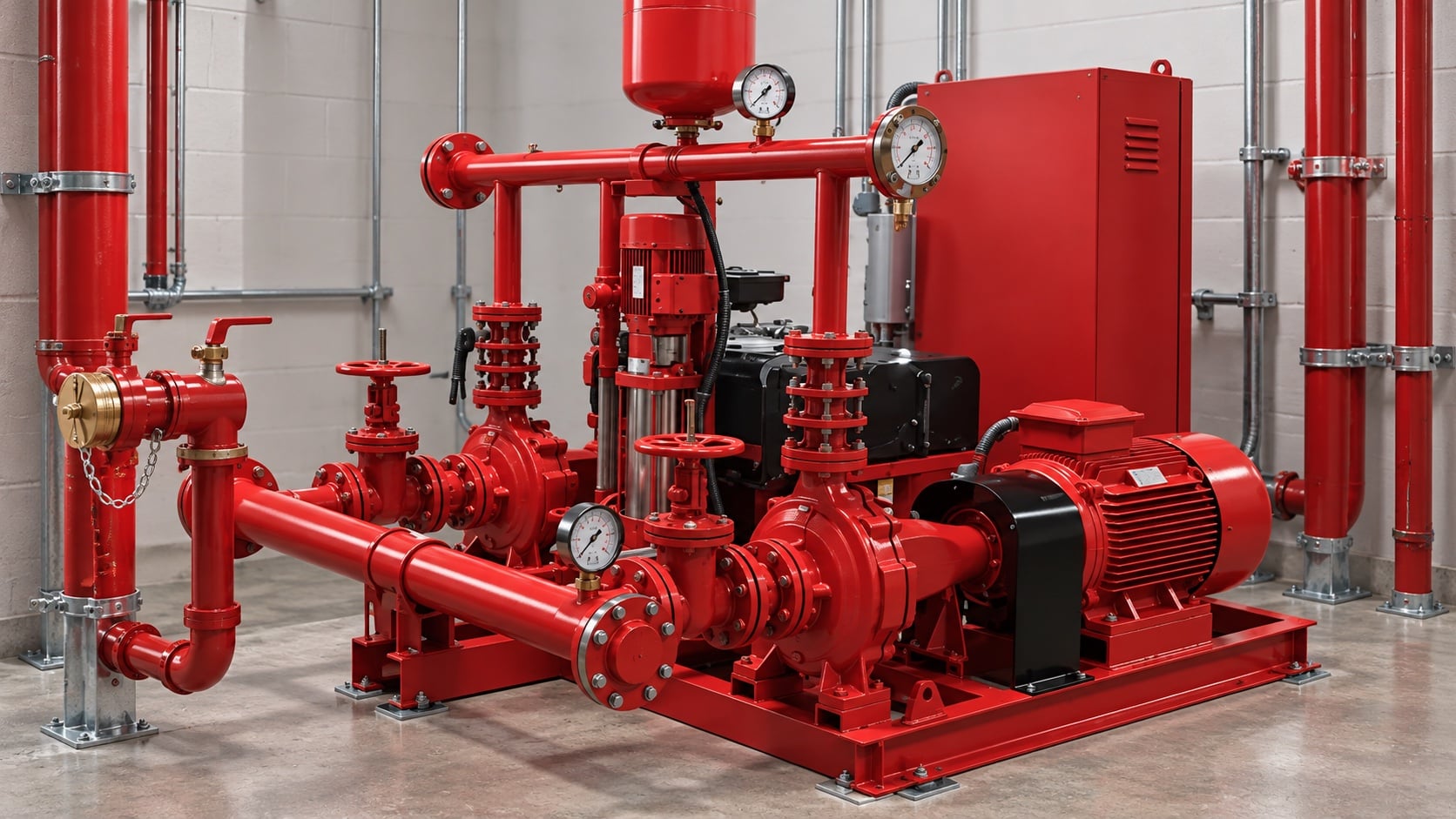
Add static elevation, friction through pipe and fittings, equipment losses, and required residual head, then subtract dependable suction head. Keep all terms in one consistent unit system. Review this condition at normal, test, and credible abnormal states before procurement. Identify the source of every input, the unit used, the operating condition it represents, and the person responsible for approval. If information is preliminary, mark the assumption and test how the decision changes at a conservative boundary. This prevents a neat calculation from hiding an uncertain water level, pressure, valve position, driver condition, or simultaneous demand.
For fire pump flow calculation, verify this section against the selected pump curve, the actual site arrangement, manufacturer instructions, and the current requirements accepted by the authority having jurisdiction. Check the installed condition as well as the drawing because pipe routes, elevations, supports, controls, and access often change during construction. Record the result in a form that can be repeated during commissioning and later inspection. Do not change a safety-critical setting or isolate fire protection without the approved impairment and restoration process.
Convert pressure and head correctly
For water, pressure and head are related through density and gravity. For other permitted liquids or unusual temperature, use actual density rather than a water shortcut. The design team should turn this point into a traceable calculation or drawing note. Identify the source of every input, the unit used, the operating condition it represents, and the person responsible for approval. If information is preliminary, mark the assumption and test how the decision changes at a conservative boundary. This prevents a neat calculation from hiding an uncertain water level, pressure, valve position, driver condition, or simultaneous demand.
For fire pump flow calculation, verify this section against the selected pump curve, the actual site arrangement, manufacturer instructions, and the current requirements accepted by the authority having jurisdiction. Check the installed condition as well as the drawing because pipe routes, elevations, supports, controls, and access often change during construction. Record the result in a form that can be repeated during commissioning and later inspection. Do not change a safety-critical setting or isolate fire protection without the approved impairment and restoration process.
ตารางการตัดสินใจเชิงปฏิบัติ
| อินพุต | ทำไมจึงสำคัญ | หลักฐานที่ต้องใช้ |
|---|---|---|
| System demand | Defines the target flow and residual pressure | การคำนวณไฮดรอลิกที่ได้รับการอนุมัติแล้ว |
| การประปา | Determines available suction pressure | Current flow test or tank data |
| Elevation | Creates static head | Verified elevations |
| Pipe and fittings | Create flow-dependent losses | As-built sizes and route |
| กราฟสมรรถนะปั๊มน้ำ | Confirms feasible duty | Manufacturer certified curve |
| Driver and power | Must carry the required load | Driver and controller data |
Check the full pump curve
Verify shutoff pressure, the rated duty point, higher-flow performance, driver loading, suction conditions, and downstream pressure limits. One point on a curve is not enough. Treat this as a system condition rather than an isolated component choice. Identify the source of every input, the unit used, the operating condition it represents, and the person responsible for approval. If information is preliminary, mark the assumption and test how the decision changes at a conservative boundary. This prevents a neat calculation from hiding an uncertain water level, pressure, valve position, driver condition, or simultaneous demand.
For fire pump flow calculation, verify this section against the selected pump curve, the actual site arrangement, manufacturer instructions, and the current requirements accepted by the authority having jurisdiction. Check the installed condition as well as the drawing because pipe routes, elevations, supports, controls, and access often change during construction. Record the result in a form that can be repeated during commissioning and later inspection. Do not change a safety-critical setting or isolate fire protection without the approved impairment and restoration process.
Coordinate zoning and pressure control
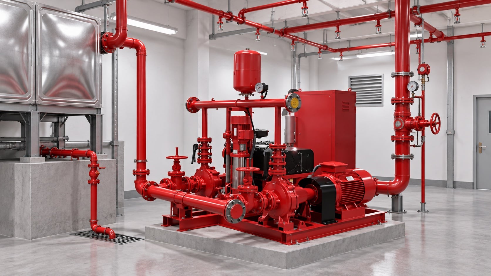
High-rise or multi-zone systems may need separate pumps, tanks, pressure-regulating devices, or staged arrangements. Do not use a relief valve as routine operating pressure control. The most useful evidence is measured or approved project data, not a copied rule of thumb. Identify the source of every input, the unit used, the operating condition it represents, and the person responsible for approval. If information is preliminary, mark the assumption and test how the decision changes at a conservative boundary. This prevents a neat calculation from hiding an uncertain water level, pressure, valve position, driver condition, or simultaneous demand.
For fire pump flow calculation, verify this section against the selected pump curve, the actual site arrangement, manufacturer instructions, and the current requirements accepted by the authority having jurisdiction. Check the installed condition as well as the drawing because pipe routes, elevations, supports, controls, and access often change during construction. Record the result in a form that can be repeated during commissioning and later inspection. Do not change a safety-critical setting or isolate fire protection without the approved impairment and restoration process.
Build a calculation package
Include demand calculations, source test, pipe model, pump curve, driver data, control sequence, valve schedule, and assumptions so another reviewer can reproduce the result. Review this condition at normal, test, and credible abnormal states before procurement. Identify the source of every input, the unit used, the operating condition it represents, and the person responsible for approval. If information is preliminary, mark the assumption and test how the decision changes at a conservative boundary. This prevents a neat calculation from hiding an uncertain water level, pressure, valve position, driver condition, or simultaneous demand.
For fire pump flow calculation, verify this section against the selected pump curve, the actual site arrangement, manufacturer instructions, and the current requirements accepted by the authority having jurisdiction. Check the installed condition as well as the drawing because pipe routes, elevations, supports, controls, and access often change during construction. Record the result in a form that can be repeated during commissioning and later inspection. Do not change a safety-critical setting or isolate fire protection without the approved impairment and restoration process.
Validate at acceptance testing
Measure suction and discharge pressure and test flow using calibrated instruments. Compare corrected results with the accepted curve and investigate any material deviation before handover. The design team should turn this point into a traceable calculation or drawing note. Identify the source of every input, the unit used, the operating condition it represents, and the person responsible for approval. If information is preliminary, mark the assumption and test how the decision changes at a conservative boundary. This prevents a neat calculation from hiding an uncertain water level, pressure, valve position, driver condition, or simultaneous demand.
For fire pump flow calculation, verify this section against the selected pump curve, the actual site arrangement, manufacturer instructions, and the current requirements accepted by the authority having jurisdiction. Check the installed condition as well as the drawing because pipe routes, elevations, supports, controls, and access often change during construction. Record the result in a form that can be repeated during commissioning and later inspection. Do not change a safety-critical setting or isolate fire protection without the approved impairment and restoration process.
สิ่งนี้เกี่ยวข้องกับอุปกรณ์ BORRAPUMP อย่างไร
BORRAPUMP เป็นผู้จัดจำหน่ายอุปกรณ์ปั๊มน้ำที่ได้รับการออกแบบทางวิศวกรรมสำหรับโครงการน้ำและระบบป้องกันอัคคีภัย โปรดตรวจสอบข้อมูลที่เกี่ยวข้อง การกำหนดค่าผลิตภัณฑ์ BORRAPUMP เพื่อใช้เป็นจุดเริ่มต้น จากนั้นจึงส่งมอบอัตราการไหล เฮด (ความสูงของน้ำ) แหล่งน้ำ ชุดขับเคลื่อน กำลังไฟฟ้า ระบบควบคุม สภาพหน้างาน ข้อกำหนดที่เกี่ยวข้อง ปริมาณ และปลายทาง การเลือกขั้นสุดท้ายต้องใช้พื้นฐานทางชลศาสตร์ของโครงการและรายการย่อยที่ได้รับการอนุมัติ คู่มือนี้ไม่ได้อ้างว่าการจัดวางตามแคตตาล็อกชุดเดียวจะเหมาะสมกับทุกเขตอำนาจศาลหรือทุกความเสี่ยง.
คู่มือ BORRAPUMP ที่เกี่ยวข้อง
ข้อมูลอ้างอิงที่เชื่อถือได้
แหล่งข้อมูลต่อไปนี้เป็นกำหนดขอบเขตมาตรฐาน บริบทด้านความปลอดภัยจากอัคคีภัย และหลักการของระบบปั๊มที่ใช้ในคู่มือฉบับนี้ ให้ใช้ฉบับพิมพ์และการบังคับใช้ท้องถิ่นที่ได้รับการยอมรับสำหรับโครงการนั้นๆ เสมอ.
- หน้าการพัฒนามาตรฐาน NFPA 20
- แหล่งข้อมูลระบบปั๊มของกระทรวงพลังงานสหรัฐฯ
- การวิจัยการป้องกันอัคคีภัยของ NIST
วิดีโอเพื่อการศึกษา

ประวัติการศึกษาโดย Practical Engineering: ปั๊มสร้างแรงดันหรือการไหล?. วิดีโอนี้สนับสนุนแนวคิดทางวิศวกรรมพื้นฐาน และไม่สามารถใช้แทนข้อกำหนดด้านการป้องกันอัคคีภัยเฉพาะของโครงการได้.
คำถามที่มักถูกถาม
Can I size a fire pump from building area?
No. Building area may influence the protection design, but the pump duty comes from the approved hydraulic demand and water supply.
Should I add suction and discharge gauge readings?
Use differential pressure across the pump, then convert it correctly to head and include elevation differences between gauge points where relevant.
What if several systems operate together?
Use the combination required by the approved design basis and authority having jurisdiction. Do not assume every demand is simultaneous or independent.
Can a larger pump provide extra safety?
Oversizing can create excessive pressure, unstable operation, and difficult testing. Select against the complete system curve and permitted pressure limits.
รายการตรวจสอบการยืนยันขั้นสุดท้าย
ก่อนการอนุมัติ ให้ตรวจสอบยืนยันเกณฑ์พื้นฐานด้านไฮดรอลิก สภาพแหล่งน้ำ กราฟปั๊มที่เลือก ข้อมูลชุดขับเคลื่อนและชุดควบคุม พิกัดความดันของส่วนประกอบ การจัดเรียงวาล์ว วิธีการทดสอบ การเข้าถึง การระบายน้ำ สัญญาณเตือน และขั้นตอนการคืนสภาพ ให้แก้ไขข้อแตกต่างระหว่างแบบแปลนและระบบที่ติดตั้งจริง ระหว่างการว่าจ้าง ให้ใช้อุปกรณ์ที่ได้รับการสอบเทียบและบันทึกความดันดูด ความดันจ่าย อัตราการไหล ความเร็ว สภาพชุดขับเคลื่อน สัญญาณเตือน และข้อสังเกตที่ผิดปกติ ณ จุดที่กำหนดทุกจุด จัดเก็บผลลัพธ์ที่ได้รับการยอมรับไว้กับบันทึกของห้องเครื่องสูบน้ำ เพื่อให้การตรวจสอบครั้ง ภายหลังสามารถเปรียบเทียบข้อมูลที่เทียบเคียงกันได้.