
Calculate fire pump flow and pressure from the approved fire-protection hydraulic demand, the available water-supply curve, elevation, pipe friction, and the residual pressure required at the controlling point. Do not select the pump by floor area, pipe diameter, or a guessed pressure alone. The required duty point must sit on a documented pump curve and the complete system must be checked at no-flow, rated-flow, and higher-flow conditions required by the governing project criteria. Keep the calculation and acceptance record with the final project documents so future tests use the same basis.
Безопасность и область применения: Пожарные насосы и их приводы относятся к оборудованию жизнеобеспечения. Работы с гидравлическими, электрическими, дизельными компонентами, топливом, аккумуляторами, под давлением, с вращающимся оборудованием, а также испытания и устранение неисправностей должны выполняться в соответствии с действующим утвержденным проектом, инструкциями производителя, применимыми стандартами и требованиями уполномоченного органа. Данное руководство описывает алгоритм принятия инженерных решений и не дает разрешения на внесение изменений на месте, обход защитных систем или эксплуатацию неквалифицированным персоналом.
- Start with the approved system demand
- Separate source pressure from pump pressure
- Calculate total dynamic head
- Convert pressure and head correctly
- Check the full pump curve
- Coordinate zoning and pressure control
- Build a calculation package
- Validate at acceptance testing
- Таблица решений
- Часто задаваемые вопросы
Start with the approved system demand
Use the hydraulic calculation for the most demanding sprinkler, standpipe, hydrant, foam, or combined scenario. Record flow, residual pressure, hose demand, duration, and which simultaneous systems are included. Treat this as a system condition rather than an isolated component choice. Identify the source of every input, the unit used, the operating condition it represents, and the person responsible for approval. If information is preliminary, mark the assumption and test how the decision changes at a conservative boundary. This prevents a neat calculation from hiding an uncertain water level, pressure, valve position, driver condition, or simultaneous demand.
For fire pump flow calculation, verify this section against the selected pump curve, the actual site arrangement, manufacturer instructions, and the current requirements accepted by the authority having jurisdiction. Check the installed condition as well as the drawing because pipe routes, elevations, supports, controls, and access often change during construction. Record the result in a form that can be repeated during commissioning and later inspection. Do not change a safety-critical setting or isolate fire protection without the approved impairment and restoration process.
Separate source pressure from pump pressure
Plot the reliable water-supply curve at the pump suction. Use the conservative available pressure at the selected flow and account for tank level, municipal variation, and suction-side losses. The most useful evidence is measured or approved project data, not a copied rule of thumb. Identify the source of every input, the unit used, the operating condition it represents, and the person responsible for approval. If information is preliminary, mark the assumption and test how the decision changes at a conservative boundary. This prevents a neat calculation from hiding an uncertain water level, pressure, valve position, driver condition, or simultaneous demand.
For fire pump flow calculation, verify this section against the selected pump curve, the actual site arrangement, manufacturer instructions, and the current requirements accepted by the authority having jurisdiction. Check the installed condition as well as the drawing because pipe routes, elevations, supports, controls, and access often change during construction. Record the result in a form that can be repeated during commissioning and later inspection. Do not change a safety-critical setting or isolate fire protection without the approved impairment and restoration process.
Calculate total dynamic head
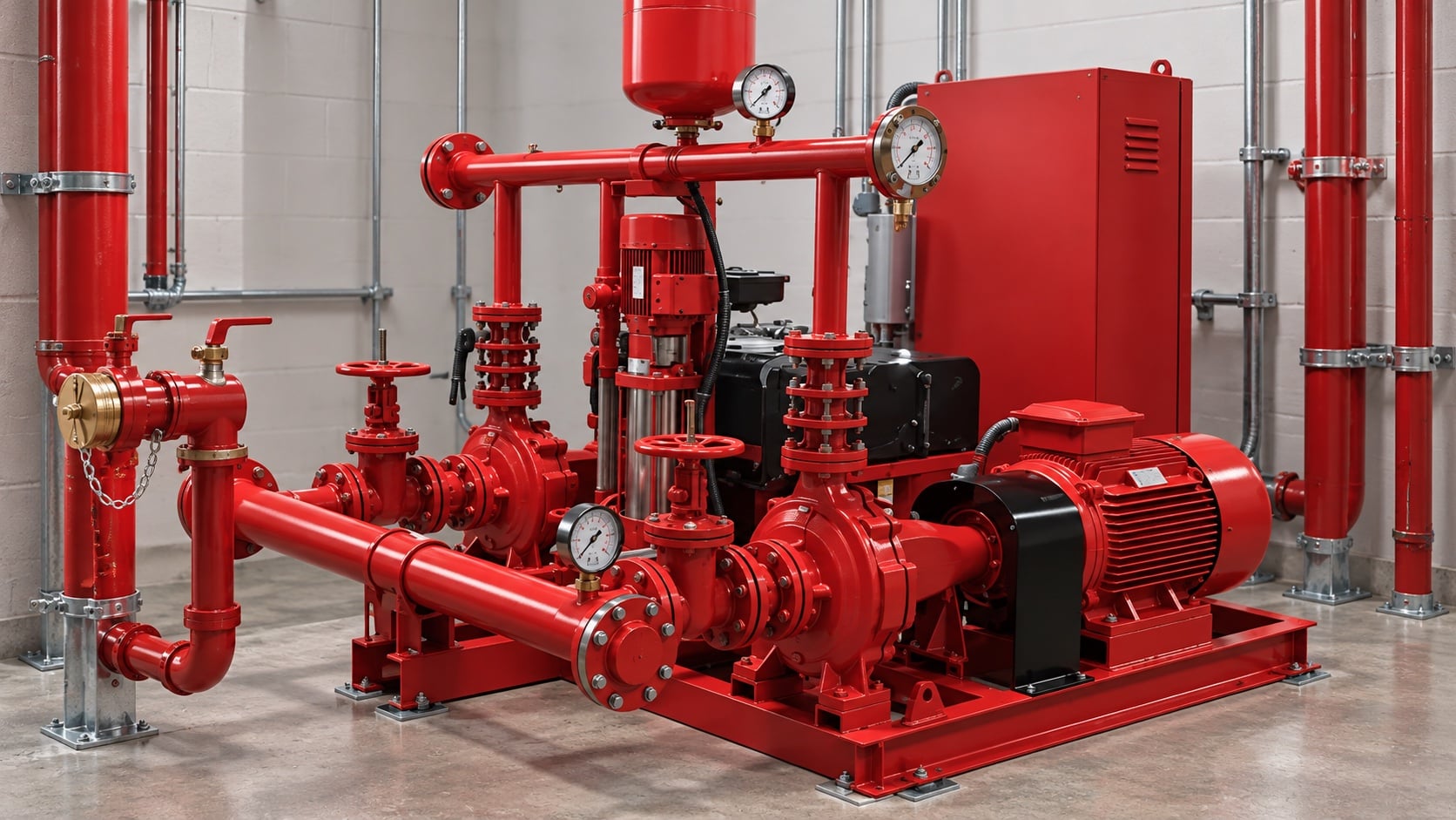
Add static elevation, friction through pipe and fittings, equipment losses, and required residual head, then subtract dependable suction head. Keep all terms in one consistent unit system. Review this condition at normal, test, and credible abnormal states before procurement. Identify the source of every input, the unit used, the operating condition it represents, and the person responsible for approval. If information is preliminary, mark the assumption and test how the decision changes at a conservative boundary. This prevents a neat calculation from hiding an uncertain water level, pressure, valve position, driver condition, or simultaneous demand.
For fire pump flow calculation, verify this section against the selected pump curve, the actual site arrangement, manufacturer instructions, and the current requirements accepted by the authority having jurisdiction. Check the installed condition as well as the drawing because pipe routes, elevations, supports, controls, and access often change during construction. Record the result in a form that can be repeated during commissioning and later inspection. Do not change a safety-critical setting or isolate fire protection without the approved impairment and restoration process.
Convert pressure and head correctly
For water, pressure and head are related through density and gravity. For other permitted liquids or unusual temperature, use actual density rather than a water shortcut. The design team should turn this point into a traceable calculation or drawing note. Identify the source of every input, the unit used, the operating condition it represents, and the person responsible for approval. If information is preliminary, mark the assumption and test how the decision changes at a conservative boundary. This prevents a neat calculation from hiding an uncertain water level, pressure, valve position, driver condition, or simultaneous demand.
For fire pump flow calculation, verify this section against the selected pump curve, the actual site arrangement, manufacturer instructions, and the current requirements accepted by the authority having jurisdiction. Check the installed condition as well as the drawing because pipe routes, elevations, supports, controls, and access often change during construction. Record the result in a form that can be repeated during commissioning and later inspection. Do not change a safety-critical setting or isolate fire protection without the approved impairment and restoration process.
Практическая таблица решений
| Ввод | Почему это важно | Требуемые доказательства |
|---|---|---|
| System demand | Defines the target flow and residual pressure | Утвержденный гидравлический расчет |
| Водоснабжение | Determines available suction pressure | Current flow test or tank data |
| Elevation | Creates static head | Verified elevations |
| Pipe and fittings | Create flow-dependent losses | As-built sizes and route |
| Напорная характеристика насоса | Confirms feasible duty | Manufacturer certified curve |
| Driver and power | Must carry the required load | Driver and controller data |
Check the full pump curve
Verify shutoff pressure, the rated duty point, higher-flow performance, driver loading, suction conditions, and downstream pressure limits. One point on a curve is not enough. Treat this as a system condition rather than an isolated component choice. Identify the source of every input, the unit used, the operating condition it represents, and the person responsible for approval. If information is preliminary, mark the assumption and test how the decision changes at a conservative boundary. This prevents a neat calculation from hiding an uncertain water level, pressure, valve position, driver condition, or simultaneous demand.
For fire pump flow calculation, verify this section against the selected pump curve, the actual site arrangement, manufacturer instructions, and the current requirements accepted by the authority having jurisdiction. Check the installed condition as well as the drawing because pipe routes, elevations, supports, controls, and access often change during construction. Record the result in a form that can be repeated during commissioning and later inspection. Do not change a safety-critical setting or isolate fire protection without the approved impairment and restoration process.
Coordinate zoning and pressure control
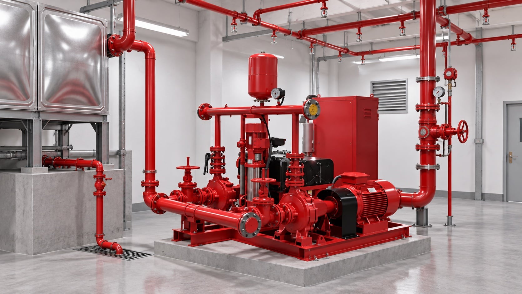
High-rise or multi-zone systems may need separate pumps, tanks, pressure-regulating devices, or staged arrangements. Do not use a relief valve as routine operating pressure control. The most useful evidence is measured or approved project data, not a copied rule of thumb. Identify the source of every input, the unit used, the operating condition it represents, and the person responsible for approval. If information is preliminary, mark the assumption and test how the decision changes at a conservative boundary. This prevents a neat calculation from hiding an uncertain water level, pressure, valve position, driver condition, or simultaneous demand.
For fire pump flow calculation, verify this section against the selected pump curve, the actual site arrangement, manufacturer instructions, and the current requirements accepted by the authority having jurisdiction. Check the installed condition as well as the drawing because pipe routes, elevations, supports, controls, and access often change during construction. Record the result in a form that can be repeated during commissioning and later inspection. Do not change a safety-critical setting or isolate fire protection without the approved impairment and restoration process.
Build a calculation package
Include demand calculations, source test, pipe model, pump curve, driver data, control sequence, valve schedule, and assumptions so another reviewer can reproduce the result. Review this condition at normal, test, and credible abnormal states before procurement. Identify the source of every input, the unit used, the operating condition it represents, and the person responsible for approval. If information is preliminary, mark the assumption and test how the decision changes at a conservative boundary. This prevents a neat calculation from hiding an uncertain water level, pressure, valve position, driver condition, or simultaneous demand.
For fire pump flow calculation, verify this section against the selected pump curve, the actual site arrangement, manufacturer instructions, and the current requirements accepted by the authority having jurisdiction. Check the installed condition as well as the drawing because pipe routes, elevations, supports, controls, and access often change during construction. Record the result in a form that can be repeated during commissioning and later inspection. Do not change a safety-critical setting or isolate fire protection without the approved impairment and restoration process.
Validate at acceptance testing
Measure suction and discharge pressure and test flow using calibrated instruments. Compare corrected results with the accepted curve and investigate any material deviation before handover. The design team should turn this point into a traceable calculation or drawing note. Identify the source of every input, the unit used, the operating condition it represents, and the person responsible for approval. If information is preliminary, mark the assumption and test how the decision changes at a conservative boundary. This prevents a neat calculation from hiding an uncertain water level, pressure, valve position, driver condition, or simultaneous demand.
For fire pump flow calculation, verify this section against the selected pump curve, the actual site arrangement, manufacturer instructions, and the current requirements accepted by the authority having jurisdiction. Check the installed condition as well as the drawing because pipe routes, elevations, supports, controls, and access often change during construction. Record the result in a form that can be repeated during commissioning and later inspection. Do not change a safety-critical setting or isolate fire protection without the approved impairment and restoration process.
Как это связано с оборудованием BORRAPUMP
BORRAPUMP поставляет насосное оборудование для проектов водоснабжения и пожаротушения. Ознакомьтесь с соответствующим Конфигурация продукта BORRAPUMP в качестве отправной точки, затем предоставьте требуемый расход, напор, источник воды, привод, мощность, средства управления, условия площадки, применимые требования, количество и пункт назначения. Окончательный выбор должен основываться на гидравлическом обосновании проекта и утвержденной проектной документации; данное руководство не утверждает, что одна каталожная компоновка подходит для любой юрисдикции или уровня риска.
Похожие руководства BORRAPUMP
- Основы проектирования систем пожарных насосов
- выбор противопожарного насоса
- дизельные и электрические пожарные насосы
Авторитетные источники
Следующие источники определяют границы стандартов, контекст пожарной безопасности и принципы работы насосных систем, используемые в данном руководстве. Всегда применяйте редакцию и местные нормы, принятые для данного проекта.
- Страница разработки стандарта NFPA 20
- Ресурсы по насосным системам Министерства энергетики США
- Исследования Национального института стандартов и технологий (NIST) в области противопожарной защиты
Обучающее видео

Образовательный бэкграунд от Practical Engineering: Создают ли насосы давление или поток?. Видео поддерживает базовую инженерную концепцию и не заменяет проектно-специфические требования пожарной безопасности.
Часто задаваемые вопросы
Can I size a fire pump from building area?
No. Building area may influence the protection design, but the pump duty comes from the approved hydraulic demand and water supply.
Should I add suction and discharge gauge readings?
Use differential pressure across the pump, then convert it correctly to head and include elevation differences between gauge points where relevant.
What if several systems operate together?
Use the combination required by the approved design basis and authority having jurisdiction. Do not assume every demand is simultaneous or independent.
Can a larger pump provide extra safety?
Oversizing can create excessive pressure, unstable operation, and difficult testing. Select against the complete system curve and permitted pressure limits.
Контрольный список финальной проверки
Перед утверждением подтвердите гидравлическое обоснование, состояние источника воды, выбранную характеристику насоса, данные привода и контроллера, номинальные давления компонентов, компоновку арматуры, метод испытаний, доступ, дренаж, аварийную сигнализацию и процедуру восстановления. Устраните расхождения между чертежами и смонтированной системой. Во время пусконаладочных работ используйте откалиброванные приборы и фиксируйте давление на входе, давление на выходе, расход, частоту вращения, состояние привода, сигналы тревоги и отклонения в каждой требуемой точке. Храните принятые результаты вместе с документацией насосной станции, чтобы при последующих проверках можно было сопоставлять сопоставимые данные.