
A fire pump relief valve can refer to a small casing relief valve that prevents pressure buildup from heat when a pump runs at little or no flow, or a larger main pressure relief valve used only where the approved fire-protection design requires it. These devices are not interchangeable. Selection and settings must follow the adopted fire code and standard, the authority having jurisdiction, the listed equipment data, pump curve, driver behavior, and the system pressure limits. A relief valve must never be used as a casual substitute for correct pump and system design.
Panduan ini adalah kerangka kerja rekayasa dan pengadaan awal, bukan pengganti desain proyek yang disetujui, peraturan yang berlaku, instruksi produsen, atau pengawasan situs yang berkualifikasi. Pekerjaan kelistrikan, pengujian bertegangan, pengangkatan, memasuki ruang terbatas, pekerjaan perlindungan kebakaran, penggalian, cairan berbahaya, air limbah, dan sistem bertekanan memerlukan prosedur khusus tugas dan personel yang kompeten. Pertahankan perlindungan otomatis dan ketersediaan sistem saat menyelidiki gangguan. Jika cairan, tugas, kondisi situs, atau persyaratan yang mengatur sebenarnya berbeda dari asumsi, hentikan dan dapatkan tinjauan teknis yang direvisi.
- Distinguish casing relief from main pressure relief
- Build the system pressure envelope
- Select listing, capacity, range, and discharge route
- Coordinate with pump, controller, and test arrangement
- Set, test, seal, and document the valve
- Inspect without defeating fire protection
- Tabel keputusan
- Pertanyaan yang sering diajukan
Distinguish casing relief from main pressure relief
A casing relief valve is typically a small device connected to the pump casing or discharge arrangement to release enough water to prevent damaging temperature rise during churn or low-flow operation. It is not sized to control the full pump discharge. A main pressure relief valve, where required or permitted by the governing design, can pass a much larger flow to limit pressure under defined conditions. The project documents should name the valve type, connection, discharge destination, listing, size, pressure range, and reason for use. Confusing the two can leave a pump without thermal protection or create an unintended large discharge. Review the current adopted edition and authority comments rather than copying a detail from another project. The pump supplier should receive the system pressure basis and the fire-protection designer should approve the final arrangement.
Build the system pressure envelope
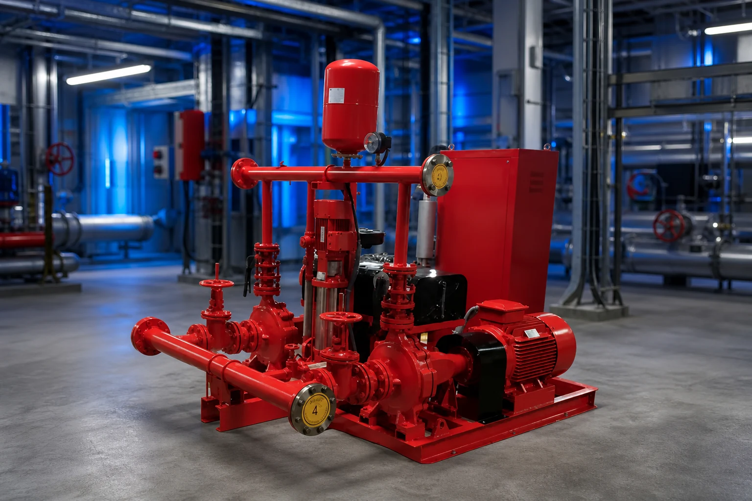
Review static suction pressure, pump rated and shutoff head, elevation, driver speed, maximum credible suction condition, test conditions, and the pressure ratings of pipe, fittings, valves, hose connections, equipment, and downstream components. For diesel-driven pumps, possible overspeed or speed variation must be addressed through the approved equipment data and design. Convert head and pressure consistently for the liquid and elevations. The relief setting cannot be chosen from the pump rated pressure alone, and it must not prevent the pump from meeting required fire-flow duty. Document normal, churn, test, and maximum credible cases. If a proposed valve setting conflicts with system ratings or required performance, resolve the pump, driver, piping, and design basis rather than treating the valve as an isolated accessory.
Select listing, capacity, range, and discharge route
Confirm that the exact valve is listed or approved as required for its fire-protection service and that size, pressure range, temperature, materials, end connections, and capacity suit the design. A main relief valve needs documented capacity at the relevant differential pressure; a casing relief valve needs the correct connection and setting range for thermal relief duty. Provide isolation only where and how the governing design allows, with supervision where required. Route discharge to a safe, visible, and acceptable location with drainage capacity, freeze protection, and protection from erosion or injury. Backpressure can affect operation and must be included when applicable. Do not discharge where water can damage electrical equipment, flood the pump room, undermine foundations, or create an unnoticed closed loop back to suction.
Tabel keputusan proyek
| Tinjau item | Casing relief valve | Main pressure relief valve |
|---|---|---|
| Tujuan utama | Limit heat buildup at low or no flow | Limit system pressure where approved design requires |
| Typical flow role | Small thermal-relief flow | Larger documented relief capacity |
| Selection basis | Pump arrangement, setting range, listing | Pressure envelope, capacity, listing, backpressure |
| Discharge concern | Visible safe drain location | Full-flow route, drainage and erosion |
| Test record | Opening and reseating under approved condition | Capacity/operation under approved test method |
Coordinate with pump, controller, and test arrangement
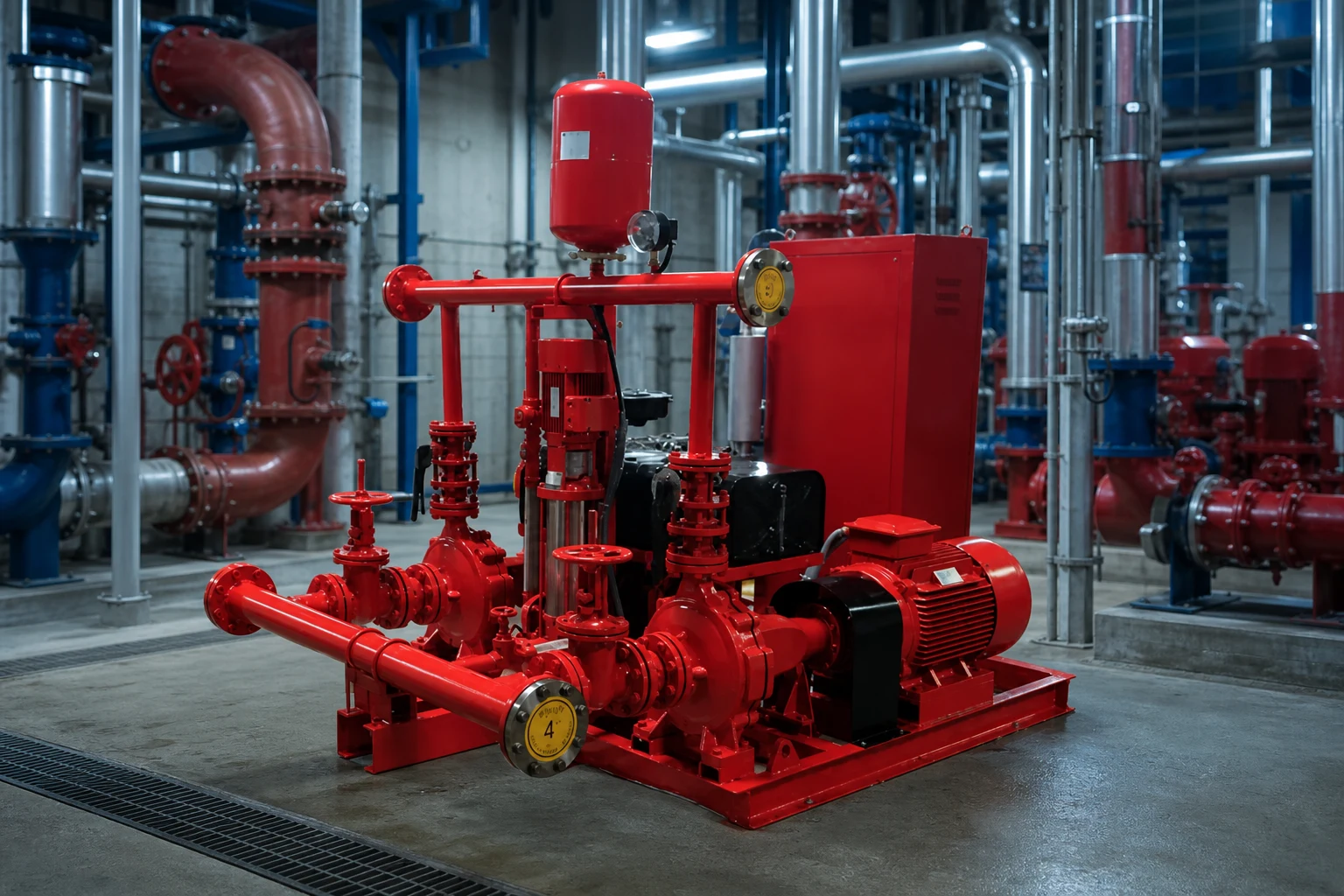
The relief valve is part of a fire pump system that includes water supply, pump, driver, controller, sensing, check and isolation valves, test header or flow meter, alarms, and room drainage. The valve arrangement must not interfere with acceptance testing or hide abnormal pump behavior. Coordinate pipe supports and valve loads with pump nozzles. The controller and alarms may need to report pump running or other conditions, but a mechanical relief valve should not be assumed to correct control settings. Review whether a variable-speed pressure-limiting control strategy is used and how its required backup and failure behavior are addressed by the approved design. Every device and set point should appear consistently on drawings, calculations, schedules, and test procedures.
Set, test, seal, and document the valve
Settings should be established by qualified personnel using calibrated instruments and the approved procedure. Record the valve identification, model, size, listed range, final setting, gauge identification, pump speed, suction pressure, discharge pressure, flow condition, discharge observation, and authority or responsible-party acceptance. Test casing relief operation under the applicable low-flow condition without allowing unsafe temperature rise. Test a main relief valve only through the approved method and with a discharge route capable of handling the flow. After adjustment, secure and seal the device as required and update the record. Never raise a setting merely to stop nuisance discharge until the cause—incorrect setting, high suction pressure, speed, blocked discharge, backpressure, or system mismatch—has been identified.
Inspect without defeating fire protection
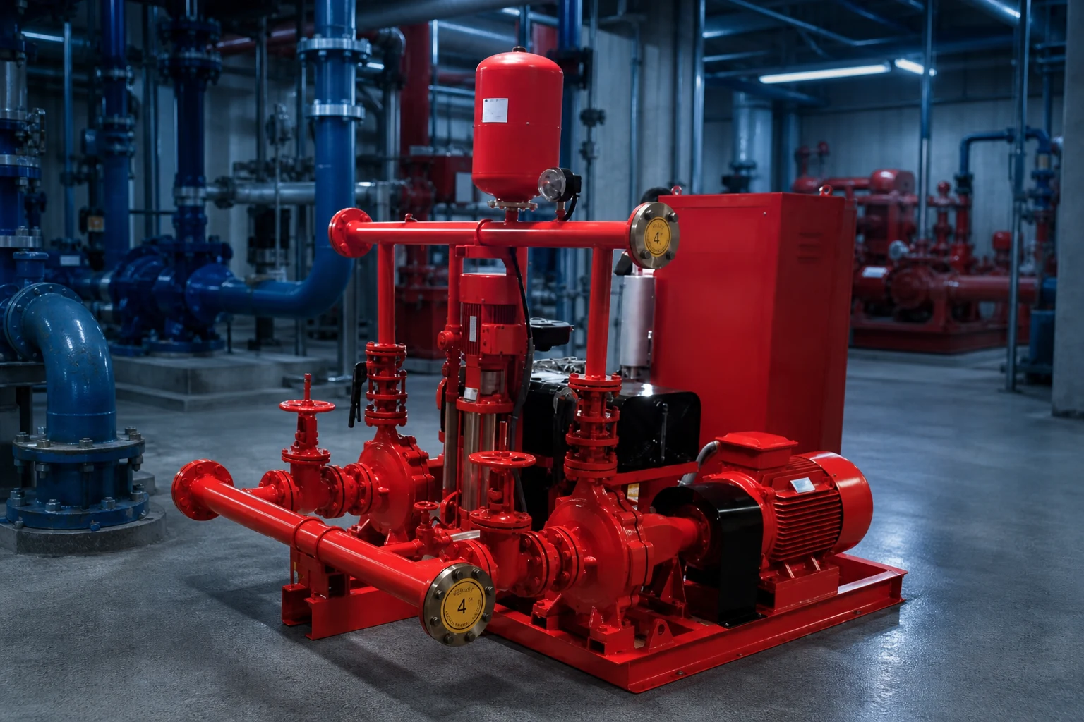
Inspection should look for leakage, corrosion, damage, blocked outlets, closed or improperly positioned valves, missing seals, changed settings, unsafe discharge, freeze exposure, and evidence of repeated operation. Maintenance frequency and test scope follow the adopted requirements, manufacturer instructions, impairment procedure, and facility program. Before isolating or servicing any fire-protection component, follow the approved impairment and notification process. Replacement is not complete until the listing, size, range, setting, discharge, and system record are verified. A relief valve that is silent may still be blocked or isolated, while one that leaks may be warning of system pressure changes. Trend observations with pump test results rather than treating the valve as a standalone plumbing item.
Catatan pengadaan dan penerimaan
Perbandingan pemasok yang lengkap harus menggunakan satu lembar data umum. Letakkan titik desain dan tugas alternatif, cairan, suhu, padatan, ketinggian lokasi, daya, kontrol, pemasangan, jam operasional, kuantitas, tujuan, dan dokumen yang diperlukan di bagian atas. Normalisasikan perbedaan cakupan sebelum membandingkan harga atau efisiensi. Minta kurva bersertifikat atau data kapasitas, daya yang diserap, batas operasional, material, dimensi, berat, sambungan, motor atau penggerak, pengendali, aksesori, pengujian, pengawetan, suku cadang, petunjuk pemasangan, dan batasan garansi. Catat setiap penyimpangan dan asumsi yang belum diselesaikan. Selama tinjauan teknis, lacak setiap fitur yang ditawarkan kembali ke masukan proyek alih-alih memberikan poin untuk fitur yang tidak dibutuhkan oleh tugas tersebut. Selama komisioning, ukur variabel yang sama yang digunakan untuk pemilihan sehingga hasil yang terpasang dapat dibandingkan dengan dasar aslinya. Jika kondisi lapangan berbeda, perbarui perhitungan dan dapatkan persetujuan yang bertanggung jawab sebelum mengubah peralatan atau pengaturan perlindungan.
Bagaimana topik ini terhubung dengan peralatan BORRAPUMP
Panduan ini mendukung peninjauan awal terhadap fire pump relief valve rute aplikasi. Ini tidak menetapkan model akhir atau mengklaim bahwa satu konfigurasi standar cocok untuk setiap proyek. Kirimkan titik tugas, data cairan, gambar lokasi, catu daya, kontrol, jumlah, tujuan, persetujuan yang diperlukan, dan lingkup inspeksi agar produk yang diusulkan dapat diperiksa terhadap servis yang sebenarnya.
Panduan teknik BORRAPUMP terkait
- Dasar-dasar desain sistem pompa pemadam kebakaran
- NFPA 20 fire pump acceptance testing
- diagram sistem pompa kebakaran
Sumber tepercaya dan pembelajaran lanjutan
Topik pompa pemadam kebakaran NFPA; OSHA fire protection; FM Global resources. Sumber-sumber ini memberikan konteks keselamatan, lingkungan, atau teknik secara umum. Aturan yang berlaku saat ini, persetujuan proyek, da petunjuk peralatan tetap menjadi pegangan utama.

Video edukasi oleh Practical Engineering: Apakah Pompa Menghasilkan Tekanan atau Aliran?. Ini menjelaskan prinsip-prinsip latar belakang dan tidak menggantikan instruksi khusus proyek.
Pertanyaan yang sering diajukan
Apakah katup pelepas *casing* sama dengan katup pelepas utama?
Tidak. Katup casing biasanya menyediakan aliran pelepas termal yang kecil; katup pelepas tekanan utama memiliki peran tekanan sistem dan kapasitas yang berbeda.
Bisakah katup pelepas mengatasi pompa pemadam kebakaran yang terlalu besar?
Ini tidak boleh digunakan sebagai pengganti sementara untuk desain pompa, penggerak, and sistem yang benar. Perancang proteksi kebakaran yang disetujui dan pihak berwenang harus meninjau dasar tekanan tersebut.
Di mana pembuangan air pelega seharusnya diarahkan?
Ke lokasi yang aman, terlihat, dan sesuai kode yang ditunjukkan oleh desain yang disetujui, dengan drainase yang memadai, perlindungan terhadap pembekuan, serta tidak menimbulkan bahaya bagi peralatan maupun orang.
Siapa yang dapat mengubah pengaturan tersebut?
Hanya personel berwenang yang berkualifikasi yang mengikuti prosedur yang disetujui, dengan instrumen yang dikalibrasi dan catatan pengujian yang diperbarui.
Titik pemeriksaan proyek akhir
Sebelum penempatan pesanan atau perubahan lapangan, selaraskan tugas dan gambar yang disetujui dengan data pemasok, material, dimensi, berat, sambungan, penggerak, kontrol, aksesori, perlindungan, lingkup pengujian, dokumentasi, suku cadang, metode pemasangan, akses pemeliharaan, dan persyaratan tujuan. Catat asumsi yang tersisa dan tetapkan tanggung jawab untuk menyelesaikannya. Informasi akhir yang diterima harus menjadi dasar yang sama yang digunakan untuk pemasangan, pengujian andal (commissioning), dan pemeliharaan di masa mendatang.