
A fire pump relief valve can refer to a small casing relief valve that prevents pressure buildup from heat when a pump runs at little or no flow, or a larger main pressure relief valve used only where the approved fire-protection design requires it. These devices are not interchangeable. Selection and settings must follow the adopted fire code and standard, the authority having jurisdiction, the listed equipment data, pump curve, driver behavior, and the system pressure limits. A relief valve must never be used as a casual substitute for correct pump and system design.
คู่มือนี้เป็นกรอบการทำงานด้านวิศวกรรมและการจัดซื้อจัดจ้างในระยะเริ่มต้น ไม่ใช่สิ่งทดแทนการออกแบบโครงการที่ได้รับอนุมัติ ข้อบังคับปัจจุบัน คำแนะนำของผู้ผลิต หรือการควบคุมดูแลหน้างานที่มีคุณสมบัติเหมาะสม งานไฟฟ้า การทดสอบที่มีกระแสไฟฟ้า การยกของ การเข้าไปในพื้นที่อับอากาศ งานป้องกันอัคคีภัย การขุดเจาะ ของเหลวอันตราย น้ำเสีย และระบบที่มีแรงดัน จำเป็นต้องมีขั้นตอนเฉพาะสำหรับงานนั้นๆ และบุคลากรที่มีความสามารถ รักษาการป้องกันอัตโนมัติและความพร้อมใช้งานของระบบในขณะที่ตรวจสอบข้อบกพร่อง หากของเหลว หน้าที่ สภาพหน้างาน หรือข้อกำหนดที่บังคับใช้จริงแตกต่างไปจากสมมติฐาน ให้หยุดทำงานและขอรับการทบทวนทางเทคนิคที่แก้ไขใหม่.
- Distinguish casing relief from main pressure relief
- Build the system pressure envelope
- Select listing, capacity, range, and discharge route
- Coordinate with pump, controller, and test arrangement
- Set, test, seal, and document the valve
- Inspect without defeating fire protection
- ตารางการตัดสินใจ
- คำถามที่มักถูกถาม
Distinguish casing relief from main pressure relief
A casing relief valve is typically a small device connected to the pump casing or discharge arrangement to release enough water to prevent damaging temperature rise during churn or low-flow operation. It is not sized to control the full pump discharge. A main pressure relief valve, where required or permitted by the governing design, can pass a much larger flow to limit pressure under defined conditions. The project documents should name the valve type, connection, discharge destination, listing, size, pressure range, and reason for use. Confusing the two can leave a pump without thermal protection or create an unintended large discharge. Review the current adopted edition and authority comments rather than copying a detail from another project. The pump supplier should receive the system pressure basis and the fire-protection designer should approve the final arrangement.
Build the system pressure envelope
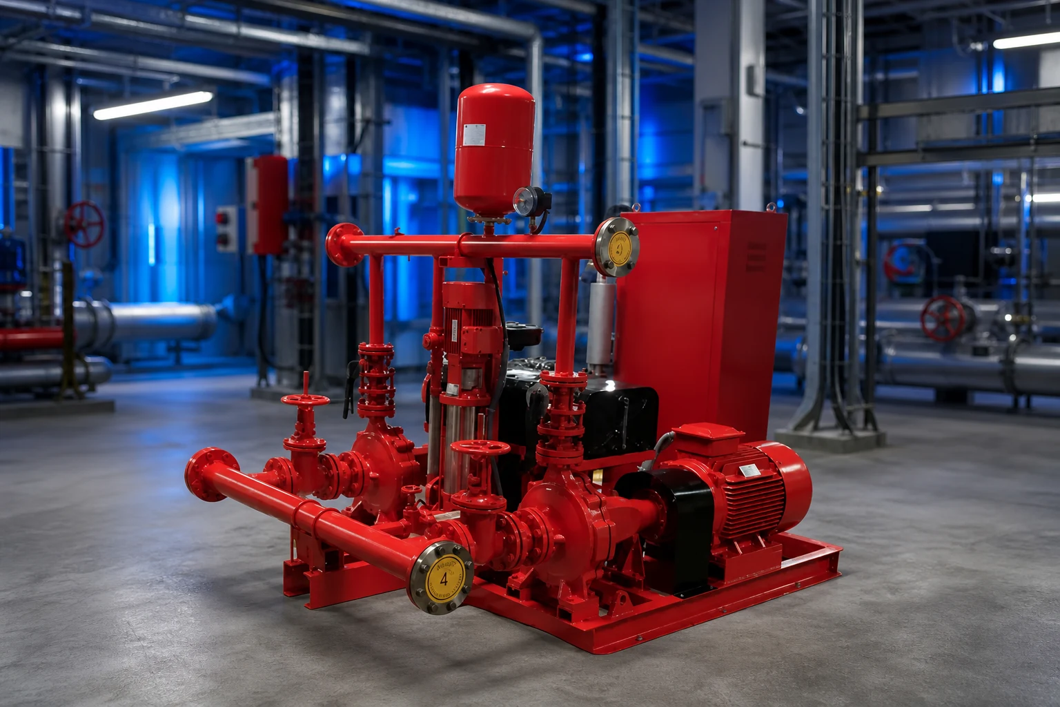
Review static suction pressure, pump rated and shutoff head, elevation, driver speed, maximum credible suction condition, test conditions, and the pressure ratings of pipe, fittings, valves, hose connections, equipment, and downstream components. For diesel-driven pumps, possible overspeed or speed variation must be addressed through the approved equipment data and design. Convert head and pressure consistently for the liquid and elevations. The relief setting cannot be chosen from the pump rated pressure alone, and it must not prevent the pump from meeting required fire-flow duty. Document normal, churn, test, and maximum credible cases. If a proposed valve setting conflicts with system ratings or required performance, resolve the pump, driver, piping, and design basis rather than treating the valve as an isolated accessory.
Select listing, capacity, range, and discharge route
Confirm that the exact valve is listed or approved as required for its fire-protection service and that size, pressure range, temperature, materials, end connections, and capacity suit the design. A main relief valve needs documented capacity at the relevant differential pressure; a casing relief valve needs the correct connection and setting range for thermal relief duty. Provide isolation only where and how the governing design allows, with supervision where required. Route discharge to a safe, visible, and acceptable location with drainage capacity, freeze protection, and protection from erosion or injury. Backpressure can affect operation and must be included when applicable. Do not discharge where water can damage electrical equipment, flood the pump room, undermine foundations, or create an unnoticed closed loop back to suction.
ตารางตัดสินใจโครงการ
| รายการตรวจสอบ | Casing relief valve | Main pressure relief valve |
|---|---|---|
| วัตถุประสงค์หลัก | Limit heat buildup at low or no flow | Limit system pressure where approved design requires |
| Typical flow role | Small thermal-relief flow | Larger documented relief capacity |
| Selection basis | Pump arrangement, setting range, listing | Pressure envelope, capacity, listing, backpressure |
| Discharge concern | Visible safe drain location | Full-flow route, drainage and erosion |
| Test record | Opening and reseating under approved condition | Capacity/operation under approved test method |
Coordinate with pump, controller, and test arrangement
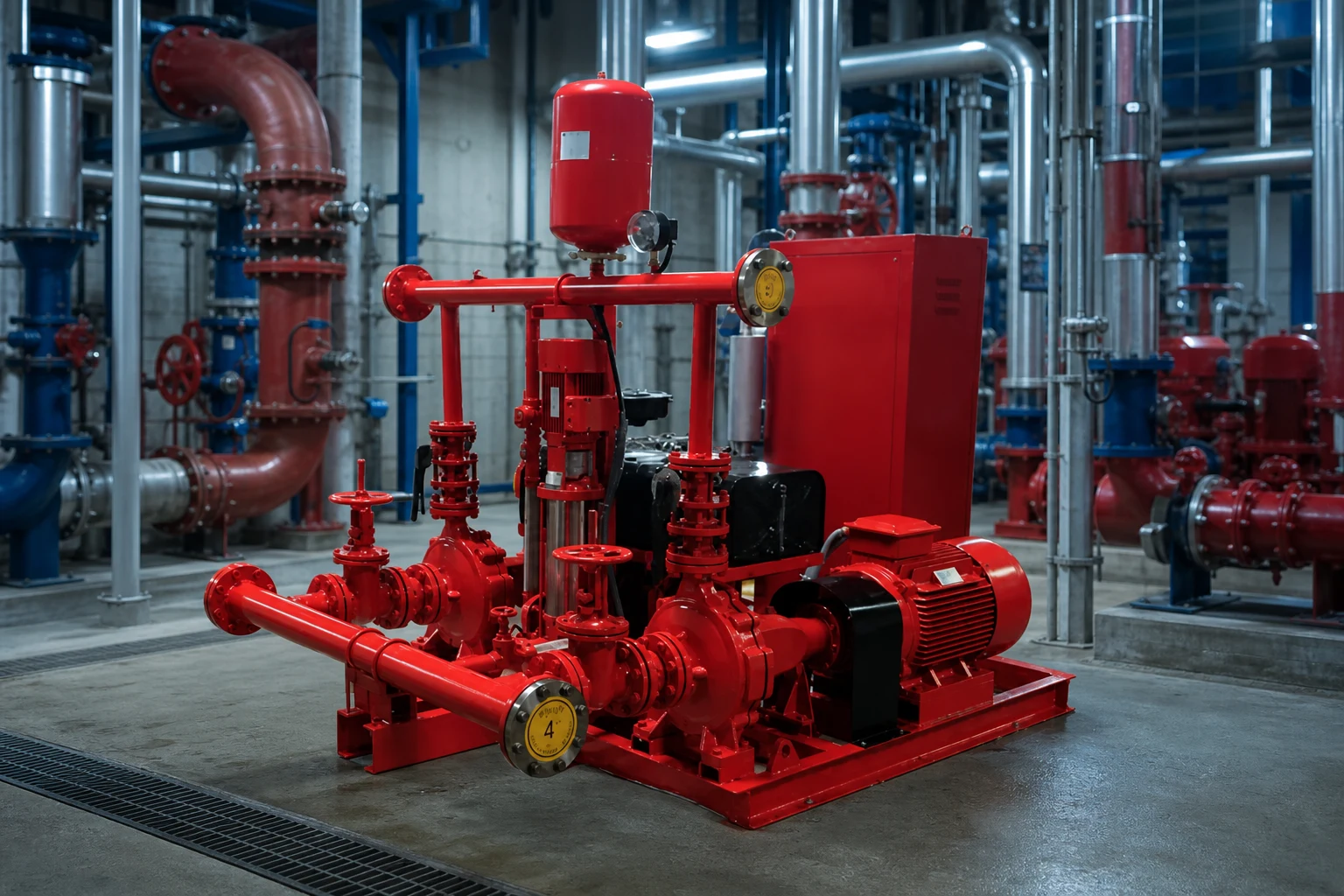
The relief valve is part of a fire pump system that includes water supply, pump, driver, controller, sensing, check and isolation valves, test header or flow meter, alarms, and room drainage. The valve arrangement must not interfere with acceptance testing or hide abnormal pump behavior. Coordinate pipe supports and valve loads with pump nozzles. The controller and alarms may need to report pump running or other conditions, but a mechanical relief valve should not be assumed to correct control settings. Review whether a variable-speed pressure-limiting control strategy is used and how its required backup and failure behavior are addressed by the approved design. Every device and set point should appear consistently on drawings, calculations, schedules, and test procedures.
Set, test, seal, and document the valve
Settings should be established by qualified personnel using calibrated instruments and the approved procedure. Record the valve identification, model, size, listed range, final setting, gauge identification, pump speed, suction pressure, discharge pressure, flow condition, discharge observation, and authority or responsible-party acceptance. Test casing relief operation under the applicable low-flow condition without allowing unsafe temperature rise. Test a main relief valve only through the approved method and with a discharge route capable of handling the flow. After adjustment, secure and seal the device as required and update the record. Never raise a setting merely to stop nuisance discharge until the cause—incorrect setting, high suction pressure, speed, blocked discharge, backpressure, or system mismatch—has been identified.
Inspect without defeating fire protection
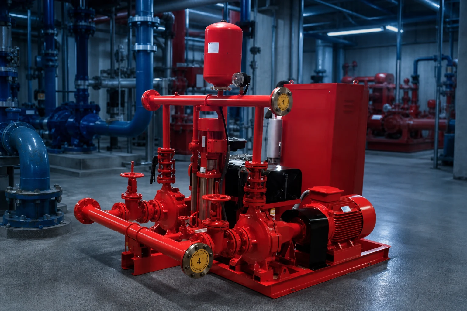
Inspection should look for leakage, corrosion, damage, blocked outlets, closed or improperly positioned valves, missing seals, changed settings, unsafe discharge, freeze exposure, and evidence of repeated operation. Maintenance frequency and test scope follow the adopted requirements, manufacturer instructions, impairment procedure, and facility program. Before isolating or servicing any fire-protection component, follow the approved impairment and notification process. Replacement is not complete until the listing, size, range, setting, discharge, and system record are verified. A relief valve that is silent may still be blocked or isolated, while one that leaks may be warning of system pressure changes. Trend observations with pump test results rather than treating the valve as a standalone plumbing item.
บันทึกการจัดซื้อและการตรวจรับ
การเปรียบเทียบผู้จำหน่ายที่สมบูรณ์ควรใช้แผ่นข้อมูลกลางชุดเดียวกัน ให้นำการออกแบบและจุดทำงานสำรอง ของเหลว อุณหภูมิ ของแข็ง ความสูงของพื้นที่ติดตั้ง กำลังไฟฟ้า ระบบควบคุม การติดตั้ง ชั่วโมงการทำงาน จำนวน ปลายทาง และเอกสารที่จำเป็น ไว้ที่ด้านบน ปรับความแตกต่างของขอบเขตให้เป็นมาตรฐานก่อนที่จะเปรียบเทียบราคาหรือประสิทธิภาพ ขอใบโค้งที่ได้รับการรับรองหรือข้อมูลสมรรถนะ กำลังไฟฟ้าที่ใช้ ขีดจำกัดการทำงาน วัสดุ ขนาด น้ำหนัก จุดเชื่อมต่อ มอเตอร์หรือชุดขับเคลื่อน ชุดควบคุม อุปกรณ์เสริม การทดสอบ การเก็บรักษา ชิ้นส่วนอะไหล่ คำแนะนำในการติดตั้ง และขอบเขตการรับประกัน บันทึกความเบี่ยงเบนและข้อสมมติที่ยังไม่ได้ข้อสรุปทุกรายการ ในระหว่างการตรวจสอบทางเทคนิค ให้สอบทานคุณสมบัติแต่ละรายการที่เสนอเข้ากับข้อมูลนำเข้าของโครงการ แทนที่จะให้คะแนนสำหรับคุณสมบัติที่หน้าที่งานไม่ได้ต้องการ ในระหว่างการทดสอบเดินระบบ ให้วัดตัวแปรชุดเดียวกันกับที่ใช้ในการคัดเลือก เพื่อให้สามารถเปรียบเทียบผลลัพธ์ที่ติดตั้งจริงกับเกณฑ์พื้นฐานเดิมได้ หากสภาพหน้างานแตกต่างไป ให้ปรับปรุงการคำนวณและขออนุมัติจากผู้รับผิดชอบก่อนที่จะเปลี่ยนอุปกรณ์หรือการตั้งค่าการป้องกัน.
หัวข้อนี้เชื่อมโยงกับอุปกรณ์ BORRAPUMP อย่างไร
คู่มือนี้สนับสนุนการตรวจสอบเบื้องต้นของ fire pump relief valve เส้นทางการสมัครใช้งาน ระบบไม่ได้กำหนดรุ่นสุดท้ายหรืออ้างว่าการกำหนดค่ามาตรฐานแบบเดียวจะเหมาะกับทุกโครงการ โปรดส่งจุดปฏิบัติงาน ข้อมูลของเหลว แบบแปลนหน้างาน แหล่งจ่ายไฟ ระบบควบคุม ปริมาณ ปลายทาง การอนุมัติที่จำเป็น และขอบเขตการตรวจสอบ เพื่อให้สามารถตรวจสอบผลิตภัณฑ์ที่เสนอเทียบกับการใช้งานจริงได้.
คู่มือวิศวกรรม BORRAPUMP ที่เกี่ยวข้อง
แหล่งข้อมูลที่เชื่อถือได้และการศึกษาเพิ่มเติม
หัวข้อปั๊มดับเพลิงตามมาตรฐาน NFPA; OSHA fire protection; FM Global resources. แหล่งข้อมูลเหล่านี้ให้บริบทด้านความปลอดภัย สิ่งแวดล้อม หรือวิศวกรรมทั่วไป กฎระเบียบที่ใช้อยู่ในปัจจุบัน การอนุมัติโครงการ และคำแนะนำเกี่ยวกับอุปกรณ์ยังคงมีผลบังคับใช้เหนือกว่า.

วิดีโอเพื่อการศึกษาโดย Practical Engineering: ปั๊มสร้างแรงดันหรือการไหล?. เอกสารนี้อธิบายหลักการเบื้องต้นและไม่ได้ใช้แทนคำแนะนำเฉพาะของโครงการ.
คำถามที่มักถูกถาม
วาล์วระบายแรงดันปลอกหุ้ม (casing relief valve) เหมือนกับวาล์วระบายแรงดันหลัก (main relief valve) หรือไม่
ไม่ใช่ โดยปกติแล้ววาล์วปลอกจะช่วยระบายความร้อนขนาดเล็ก ส่วนวาล์วระบายความแรงดันหลักจะมีหน้าที่เกี่ยวกับแรงดันในระบบและความสามารถในการรองรับที่แตกต่างกัน.
วาล์วระบายแรงดันสามารถแก้ไขปัญหาเครื่องสูบน้ำดับเพลิงที่มีขนาดใหญ่เกินไปได้หรือไม่
ไม่ควรนำมาใช้เป็นตัวแทนทั่วไปสำหรับการออกแบบปั๊ม ตัวขับเคลื่อน และระบบที่ถูกต้อง ผู้ออกแบบระบบป้องกันอัคคีภัยที่ได้รับอนุมัติและผู้มีอำนาจหน้าที่ต้องตรวจสอบพื้นฐานความดัน.
ควรระบายน้ำบรรเทาทุกข์ไปที่ไหน
ไปยังตำแหน่งที่ปลอดภัย มองเห็นได้ และเป็นไปตามรหัสซึ่งแสดงโดยแบบที่ได้รับการอนุมัติ พร้อมการระบายน้ำที่เพียงพอ การป้องกันการแข็งตัว และไม่มีอันตรายต่ออุปกรณ์หรือผู้คน.
ใครสามารถเปลี่ยนการตั้งค่าได้บ้าง
Only qualified authorized personnel following the approved procedure, with calibrated instruments and updated test records.
จุดตรวจสอบโครงงานสุดท้าย
ก่อนทำการสั่งซื้อหรือเปลี่ยนแปลงหน้างาน ให้ตรวจสอบความถูกต้องตรงกันระหว่างหน้าที่และแบบที่ได้รับการอนุมัติ กับข้อมูลของผู้จำหน่าย วัสดุ ขนาด น้ำหนัก จุดเชื่อมต่อ ไดรฟ์ ชุดควบคุม อุปกรณ์เสริม ระบบป้องกัน ขอบเขตการทดสอบ เอกสาร ชิ้นส่วนอะไหล่ วิธีการติดตั้ง การเข้าถึงเพื่อการบำรุงรักษา และข้อกำหนดของปลายทาง บันทึกข้อสมมติฐานที่เหลืออยู่และกำหนดผู้รับผิดชอบในการปิดประเด็นเหล่านั้น ข้อมูลที่ได้รับการยอมรับขั้นสุดท้ายจะต้องใช้เป็นพื้นฐานเดียวกันสำหรับการติดตั้ง การทดสอบการเดินระบบ และการบำรุงรักษาในอนาคต.