
A fire pump relief valve can refer to a small casing relief valve that prevents pressure buildup from heat when a pump runs at little or no flow, or a larger main pressure relief valve used only where the approved fire-protection design requires it. These devices are not interchangeable. Selection and settings must follow the adopted fire code and standard, the authority having jurisdiction, the listed equipment data, pump curve, driver behavior, and the system pressure limits. A relief valve must never be used as a casual substitute for correct pump and system design.
هذا الدليل هو إطار هندسي ومشتريات مبكر، وليس بديلاً عن تصميم المشروع المعتمد، أو اللوائح الحالية، أو تعليمات الشركة المصنعة، أو إشراف الموقع المؤهل. تتطلب الأعمال الكهربائية، والاختبارات تحت الجهد، والرفع، والعمل في الأماكن المغلقة، وأعمال الحماية من الحريق، والحفر، والسوائل الخطرة، ومياه الصرف الصحي، والأنظمة المضغوطة إجراءات خاصة بالمهمة وأفراداً أثبتا كفاءتهم. حافظ على الحماية التلقائية وتوفر النظام أثناء التحقيق في الأعطال. إذا كان السائل الفعلي، أو الواجب، أو حالة الموقع، أو المتطلبات الحاكمة تختلف عن الافتراضات، فتوقف واحصل على مراجعة فنية معدلة.
- Distinguish casing relief from main pressure relief
- Build the system pressure envelope
- Select listing, capacity, range, and discharge route
- Coordinate with pump, controller, and test arrangement
- Set, test, seal, and document the valve
- Inspect without defeating fire protection
- جدول القرار
- الأسئلة الشائعة
Distinguish casing relief from main pressure relief
A casing relief valve is typically a small device connected to the pump casing or discharge arrangement to release enough water to prevent damaging temperature rise during churn or low-flow operation. It is not sized to control the full pump discharge. A main pressure relief valve, where required or permitted by the governing design, can pass a much larger flow to limit pressure under defined conditions. The project documents should name the valve type, connection, discharge destination, listing, size, pressure range, and reason for use. Confusing the two can leave a pump without thermal protection or create an unintended large discharge. Review the current adopted edition and authority comments rather than copying a detail from another project. The pump supplier should receive the system pressure basis and the fire-protection designer should approve the final arrangement.
Build the system pressure envelope
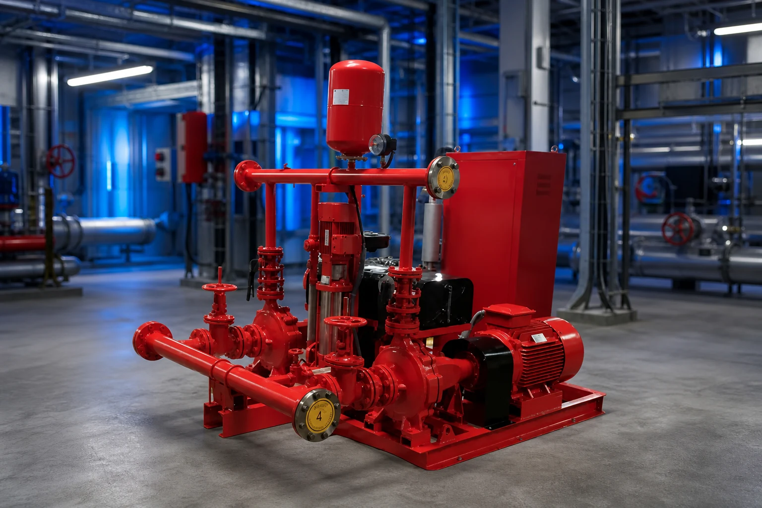
Review static suction pressure, pump rated and shutoff head, elevation, driver speed, maximum credible suction condition, test conditions, and the pressure ratings of pipe, fittings, valves, hose connections, equipment, and downstream components. For diesel-driven pumps, possible overspeed or speed variation must be addressed through the approved equipment data and design. Convert head and pressure consistently for the liquid and elevations. The relief setting cannot be chosen from the pump rated pressure alone, and it must not prevent the pump from meeting required fire-flow duty. Document normal, churn, test, and maximum credible cases. If a proposed valve setting conflicts with system ratings or required performance, resolve the pump, driver, piping, and design basis rather than treating the valve as an isolated accessory.
Select listing, capacity, range, and discharge route
Confirm that the exact valve is listed or approved as required for its fire-protection service and that size, pressure range, temperature, materials, end connections, and capacity suit the design. A main relief valve needs documented capacity at the relevant differential pressure; a casing relief valve needs the correct connection and setting range for thermal relief duty. Provide isolation only where and how the governing design allows, with supervision where required. Route discharge to a safe, visible, and acceptable location with drainage capacity, freeze protection, and protection from erosion or injury. Backpressure can affect operation and must be included when applicable. Do not discharge where water can damage electrical equipment, flood the pump room, undermine foundations, or create an unnoticed closed loop back to suction.
جدول قرار المشروع
| عنصر مراجعة | Casing relief valve | Main pressure relief valve |
|---|---|---|
| الغرض الأساسي | Limit heat buildup at low or no flow | Limit system pressure where approved design requires |
| Typical flow role | Small thermal-relief flow | Larger documented relief capacity |
| Selection basis | Pump arrangement, setting range, listing | Pressure envelope, capacity, listing, backpressure |
| Discharge concern | Visible safe drain location | Full-flow route, drainage and erosion |
| Test record | Opening and reseating under approved condition | Capacity/operation under approved test method |
Coordinate with pump, controller, and test arrangement
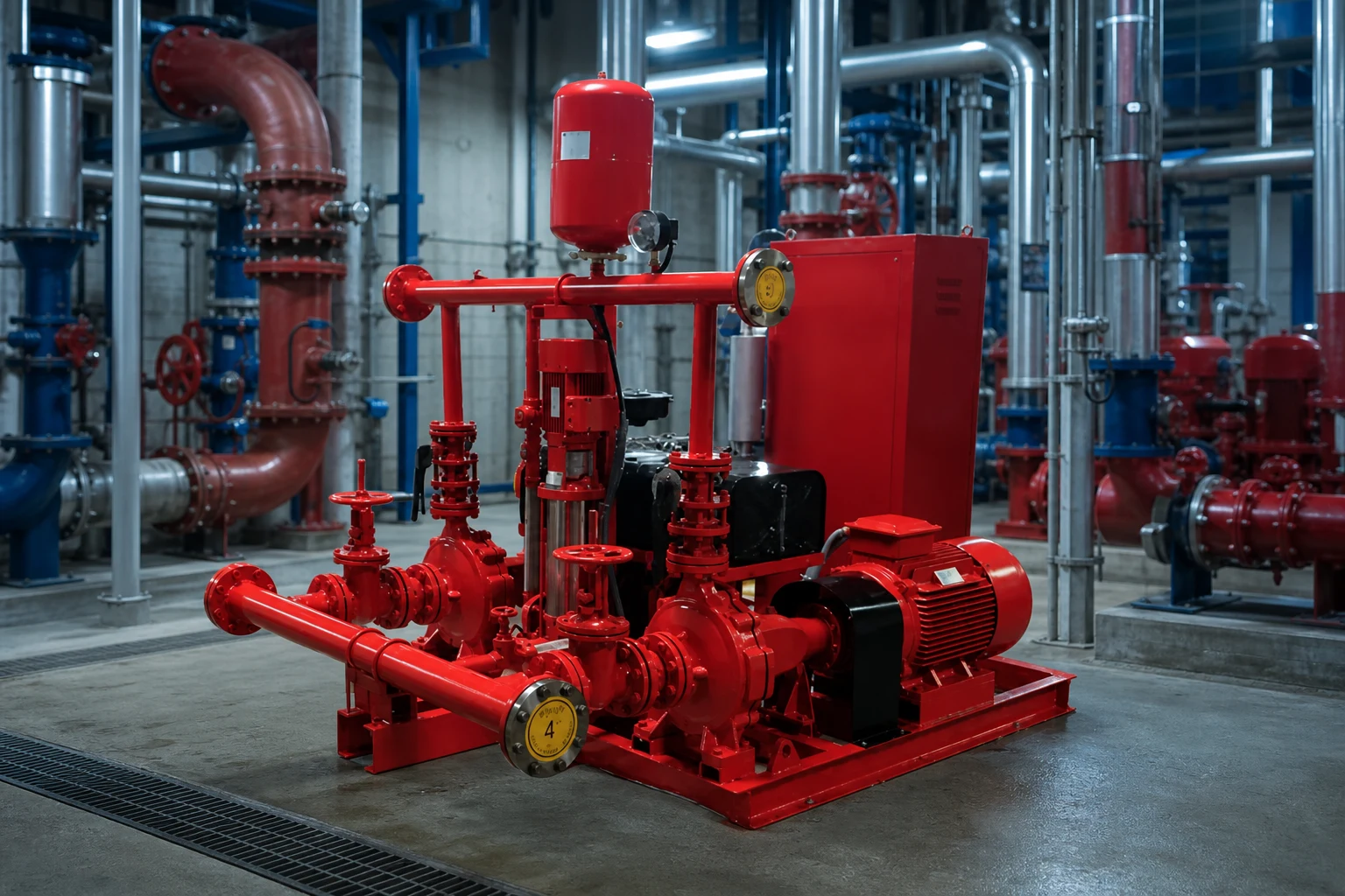
The relief valve is part of a fire pump system that includes water supply, pump, driver, controller, sensing, check and isolation valves, test header or flow meter, alarms, and room drainage. The valve arrangement must not interfere with acceptance testing or hide abnormal pump behavior. Coordinate pipe supports and valve loads with pump nozzles. The controller and alarms may need to report pump running or other conditions, but a mechanical relief valve should not be assumed to correct control settings. Review whether a variable-speed pressure-limiting control strategy is used and how its required backup and failure behavior are addressed by the approved design. Every device and set point should appear consistently on drawings, calculations, schedules, and test procedures.
Set, test, seal, and document the valve
Settings should be established by qualified personnel using calibrated instruments and the approved procedure. Record the valve identification, model, size, listed range, final setting, gauge identification, pump speed, suction pressure, discharge pressure, flow condition, discharge observation, and authority or responsible-party acceptance. Test casing relief operation under the applicable low-flow condition without allowing unsafe temperature rise. Test a main relief valve only through the approved method and with a discharge route capable of handling the flow. After adjustment, secure and seal the device as required and update the record. Never raise a setting merely to stop nuisance discharge until the cause—incorrect setting, high suction pressure, speed, blocked discharge, backpressure, or system mismatch—has been identified.
Inspect without defeating fire protection
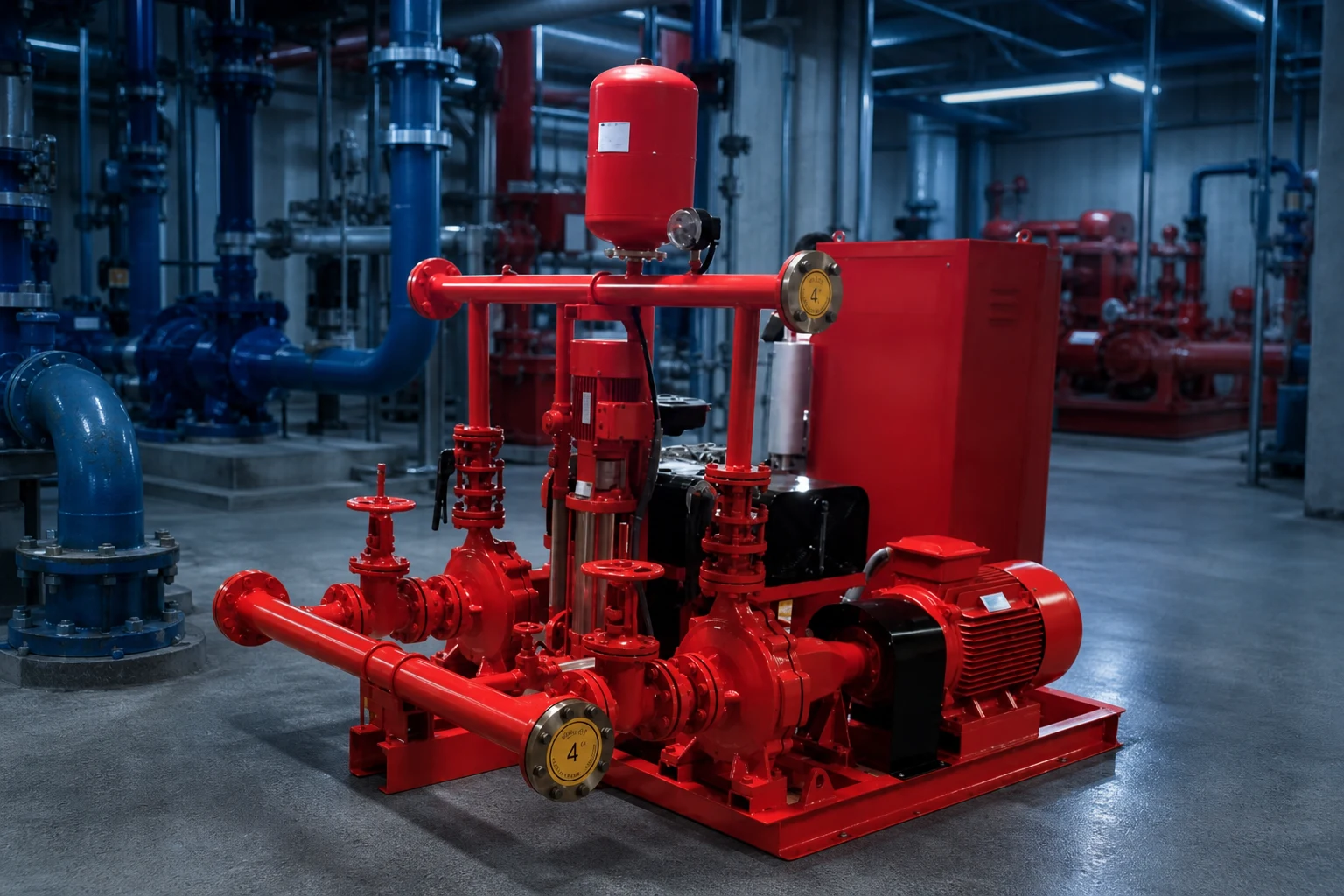
Inspection should look for leakage, corrosion, damage, blocked outlets, closed or improperly positioned valves, missing seals, changed settings, unsafe discharge, freeze exposure, and evidence of repeated operation. Maintenance frequency and test scope follow the adopted requirements, manufacturer instructions, impairment procedure, and facility program. Before isolating or servicing any fire-protection component, follow the approved impairment and notification process. Replacement is not complete until the listing, size, range, setting, discharge, and system record are verified. A relief valve that is silent may still be blocked or isolated, while one that leaks may be warning of system pressure changes. Trend observations with pump test results rather than treating the valve as a standalone plumbing item.
سجل الشراء والقبول
يجب أن تستخدم مقارنة الموردين الكاملة ورقة بيانات عامة واحدة. ضع نقاط التصميم والتشغيل البديلة، السائل، درجة الحرارة، المواد الصلبة، ارتفاع الموقع، الطاقة، أدوات التحكم، التركيب، ساعات التشغيل، الكمية، الوجهة، والمستندات المطلوبة في الأعلى. قم بتوحيد الاختلافات في النطاق قبل مقارنة السعر أو الكفاءة. اطلب منحنى معتمدًا أو بيانات سعة، والطاقة الممتصة، حدود التشغيل، المواد، الأبعاد، الوزن، الوصلات، المحرك أو المشغل، وحدة التحكم، الملحقات، الاختبارات، الحفظ، قطع الغيار، تعليمات التركيب، وحدود الضمان. سجل كل انحراف وافتراض غير محلل. أثناء المراجعة الفنية، تتبع كل ميزة معروضة وصولاً إلى مدخلات المشروع بدلاً من منح نقاط لميزات لا يحتاجها واجب العمل. أثناء التشغيل التجريبي، قس نفس المتغيرات المستخدمة في الاختيار بحيث يمكن مقارنة النتيجة المثبتة مع الأساس الأصلي. إذا كانت ظروف الموقع مختلفة، قم بتحديث الحساب واجصل على موافقة مسؤولة قبل تغيير المعدات أو إعدادات الحماية.
كيف يرتبط هذا الموضوع بمعدات BORRAPUMP
يدعم هذا الدليل المراجعة المبكرة لـ fire pump relief valve مسار التطبيق. إنه لا يعين نموذجاً نهائياً أو يدعي أن تكوينًا قياسيًا واحدًا يناسب كل مشروع. أرسل نقاط التشغيل، والبيانات السائلة، ومخطط الموقع، ومصدر الطاقة، وأدوات التحكم، والكمية، والوجهة، والموافقات المطلوبة، ونطاق الفحص بحيث يمكن التحقق من المنتج المقترح مقابل الخدمة الحقيقية.
أدلة الهندسة الخاصة بـ BORRAPUMP ذات الصلة
مصادر موثوقة ومزيد من التعلم
مضخات الحريق حسب معايير الرابطة الوطنية للحماية من الحريق (NFPA); OSHA fire protection; FM Global resources. توفر هذه المصادر سياقاً عاماً للسلامة أو البيئة أو الهندسة. تظل القواعد الحالية المعتمدة، ووافقات المشاريع، وتعليمات المعدات هي التي تحكم.

فيديو تعليمي من إنتاج براكتيكال إنجينيرينغ: هل المضخات تولد ضغطاً أم تدفقاً؟. إنه يوضح المبادئ الأساسية ولا يحل محل التعليمات الخاصة بالمشروع.
الأسئلة الشائعة
هل صمام تخفيف الغلاف هو نفس الصمام الرئيسي لتخفيف الضغط؟
لا. يوفر صمام الغلاف عادةً تدفقاً بسيطاً لتفريغ الضغط الحراري؛ بينما يمتلك صمام تخفيف الضغط الرئيسي دوراً مختلفاً فيما يتعلق بضغط النظام وسعته.
هل يمكن لصمام تخفيف الضغط إصلاح مضخة حريق ذات حجم أكبر من اللازم؟
لا ينبغي استخدامه كبديل عرضي للتصميم الصحيح للمضخة والمشغل والنظام. يجب على مصمم الحماية من الحريق المعتمد والسلطة المختصة مراجعة أساس الضغط.
أين يجب أن تصب مياه الإغاثة؟
إلى الموقع الآمن والمرئي والموافق للكود الموضح في التصميم المعتمد، مع تصريف مناسب، وحماية من التجمد، وبدون أي خطر على المعدات أو الأشخاص.
من يمكنه تغيير الإعداد؟
Only qualified authorized personnel following the approved procedure, with calibrated instruments and updated test records.
نقطة تفتيش المشروع النهائي
قبل تأكيد الطلب أو إجراء أي تغيير ميداني، قم بمطابقة الواجب والمخططات المعتمدة مع بيانات المورد، والمواد، والأبعاد، والأوزان، والوصلات، ومشغل التشغيل، وأدوات التحكم، والملحقات، الحماية، ونطاق الاختبار، والوثائق، وقطع الغيار، وطريقة التركيب، وإمكانية الوصول للصيانة، ومتطلبات وجهة الوصول. قم بتسجيل الافتراضات المتبقية وتحديد المسؤولية عن إغلاقها. يجب أن تكون المعلومات النهائية المقبولة هي الأساس ذاته المستخدم للتركيب، والتشغيل التجريبي، والصيانة المستقبلية.