
A fire pump relief valve can refer to a small casing relief valve that prevents pressure buildup from heat when a pump runs at little or no flow, or a larger main pressure relief valve used only where the approved fire-protection design requires it. These devices are not interchangeable. Selection and settings must follow the adopted fire code and standard, the authority having jurisdiction, the listed equipment data, pump curve, driver behavior, and the system pressure limits. A relief valve must never be used as a casual substitute for correct pump and system design.
Bu kılavuz, onaylı proje tasarımının, yürürlükteki yönetmeliklerin, üretici talimatlarının veya yetkili saha denetiminin yerini almayan erken aşamalı bir mühendislik ve tedarik çerçevesidir; elektrik işleri, enerjili testler, kaldırma, kapalı alan çalışmaları, yangından korunma çalışmaları, kazı, tehlikeli sıvılar, atık su ve basınçlı sistemler, görev odaklı prosedürler ve yetkin personel gerektirir. Arızaları araştırırken otomatik korumayı ve sistem kullanılabilirliğini koruyun. Gerçek sıvı, görev, saha koşulu veya geçerli gereklilik varsayımlardan farklıysa, durun ve gözden geçirilmiş bir teknik inceleme elde edin.
- Distinguish casing relief from main pressure relief
- Build the system pressure envelope
- Select listing, capacity, range, and discharge route
- Coordinate with pump, controller, and test arrangement
- Set, test, seal, and document the valve
- Inspect without defeating fire protection
- Karar tablosu
- Sık sorulan sorular
Distinguish casing relief from main pressure relief
A casing relief valve is typically a small device connected to the pump casing or discharge arrangement to release enough water to prevent damaging temperature rise during churn or low-flow operation. It is not sized to control the full pump discharge. A main pressure relief valve, where required or permitted by the governing design, can pass a much larger flow to limit pressure under defined conditions. The project documents should name the valve type, connection, discharge destination, listing, size, pressure range, and reason for use. Confusing the two can leave a pump without thermal protection or create an unintended large discharge. Review the current adopted edition and authority comments rather than copying a detail from another project. The pump supplier should receive the system pressure basis and the fire-protection designer should approve the final arrangement.
Build the system pressure envelope
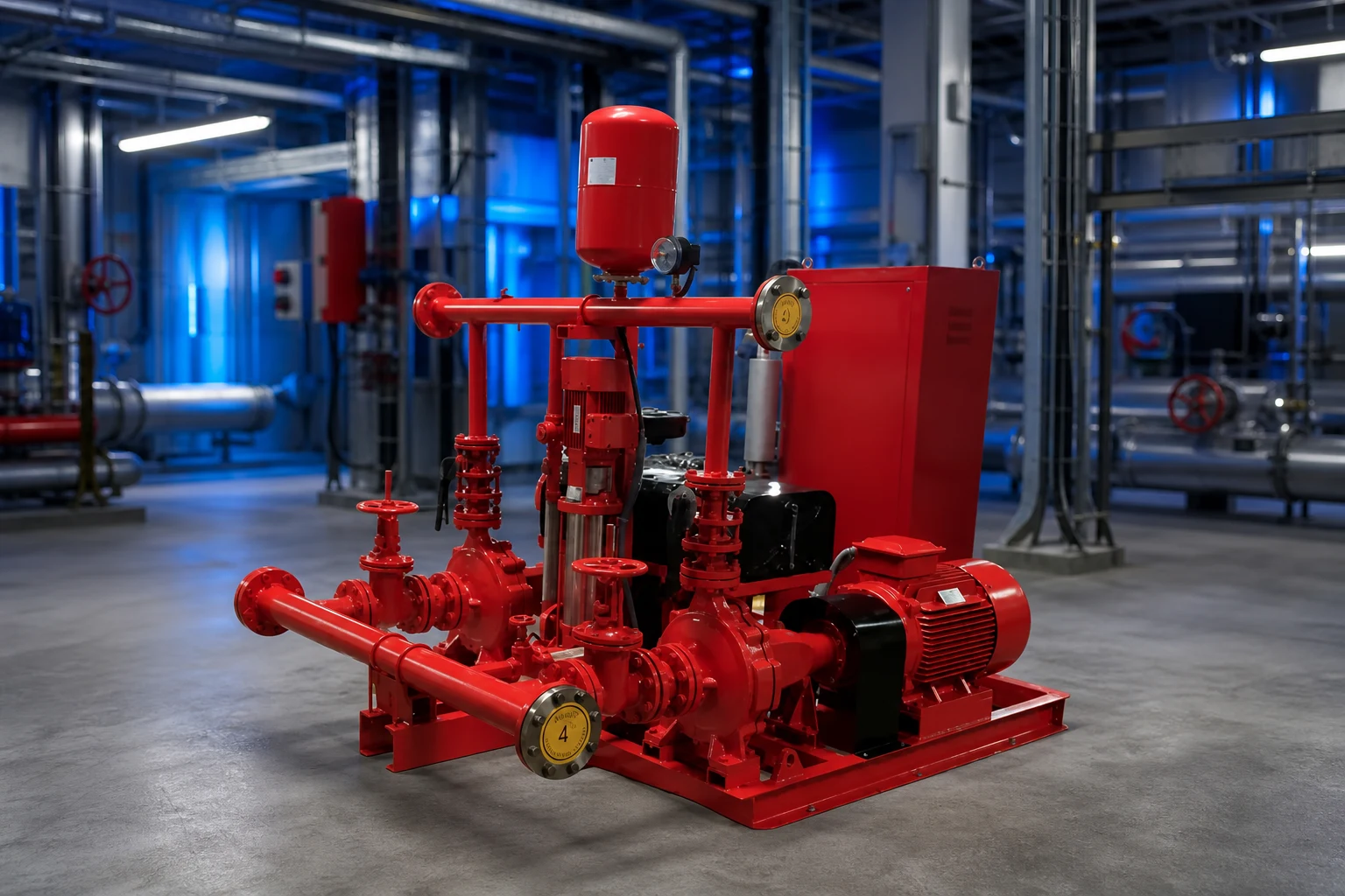
Review static suction pressure, pump rated and shutoff head, elevation, driver speed, maximum credible suction condition, test conditions, and the pressure ratings of pipe, fittings, valves, hose connections, equipment, and downstream components. For diesel-driven pumps, possible overspeed or speed variation must be addressed through the approved equipment data and design. Convert head and pressure consistently for the liquid and elevations. The relief setting cannot be chosen from the pump rated pressure alone, and it must not prevent the pump from meeting required fire-flow duty. Document normal, churn, test, and maximum credible cases. If a proposed valve setting conflicts with system ratings or required performance, resolve the pump, driver, piping, and design basis rather than treating the valve as an isolated accessory.
Select listing, capacity, range, and discharge route
Confirm that the exact valve is listed or approved as required for its fire-protection service and that size, pressure range, temperature, materials, end connections, and capacity suit the design. A main relief valve needs documented capacity at the relevant differential pressure; a casing relief valve needs the correct connection and setting range for thermal relief duty. Provide isolation only where and how the governing design allows, with supervision where required. Route discharge to a safe, visible, and acceptable location with drainage capacity, freeze protection, and protection from erosion or injury. Backpressure can affect operation and must be included when applicable. Do not discharge where water can damage electrical equipment, flood the pump room, undermine foundations, or create an unnoticed closed loop back to suction.
Proje karar tablosu
| İnceleme öğesi | Casing relief valve | Main pressure relief valve |
|---|---|---|
| Birincil amaç | Limit heat buildup at low or no flow | Limit system pressure where approved design requires |
| Typical flow role | Small thermal-relief flow | Larger documented relief capacity |
| Selection basis | Pump arrangement, setting range, listing | Pressure envelope, capacity, listing, backpressure |
| Discharge concern | Visible safe drain location | Full-flow route, drainage and erosion |
| Test record | Opening and reseating under approved condition | Capacity/operation under approved test method |
Coordinate with pump, controller, and test arrangement
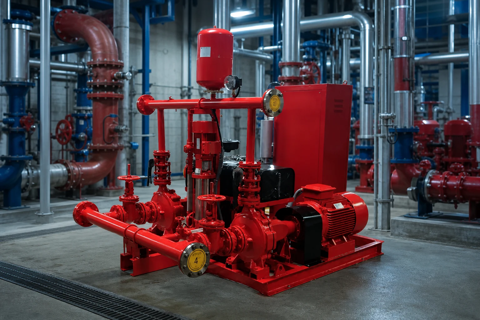
The relief valve is part of a fire pump system that includes water supply, pump, driver, controller, sensing, check and isolation valves, test header or flow meter, alarms, and room drainage. The valve arrangement must not interfere with acceptance testing or hide abnormal pump behavior. Coordinate pipe supports and valve loads with pump nozzles. The controller and alarms may need to report pump running or other conditions, but a mechanical relief valve should not be assumed to correct control settings. Review whether a variable-speed pressure-limiting control strategy is used and how its required backup and failure behavior are addressed by the approved design. Every device and set point should appear consistently on drawings, calculations, schedules, and test procedures.
Set, test, seal, and document the valve
Settings should be established by qualified personnel using calibrated instruments and the approved procedure. Record the valve identification, model, size, listed range, final setting, gauge identification, pump speed, suction pressure, discharge pressure, flow condition, discharge observation, and authority or responsible-party acceptance. Test casing relief operation under the applicable low-flow condition without allowing unsafe temperature rise. Test a main relief valve only through the approved method and with a discharge route capable of handling the flow. After adjustment, secure and seal the device as required and update the record. Never raise a setting merely to stop nuisance discharge until the cause—incorrect setting, high suction pressure, speed, blocked discharge, backpressure, or system mismatch—has been identified.
Inspect without defeating fire protection
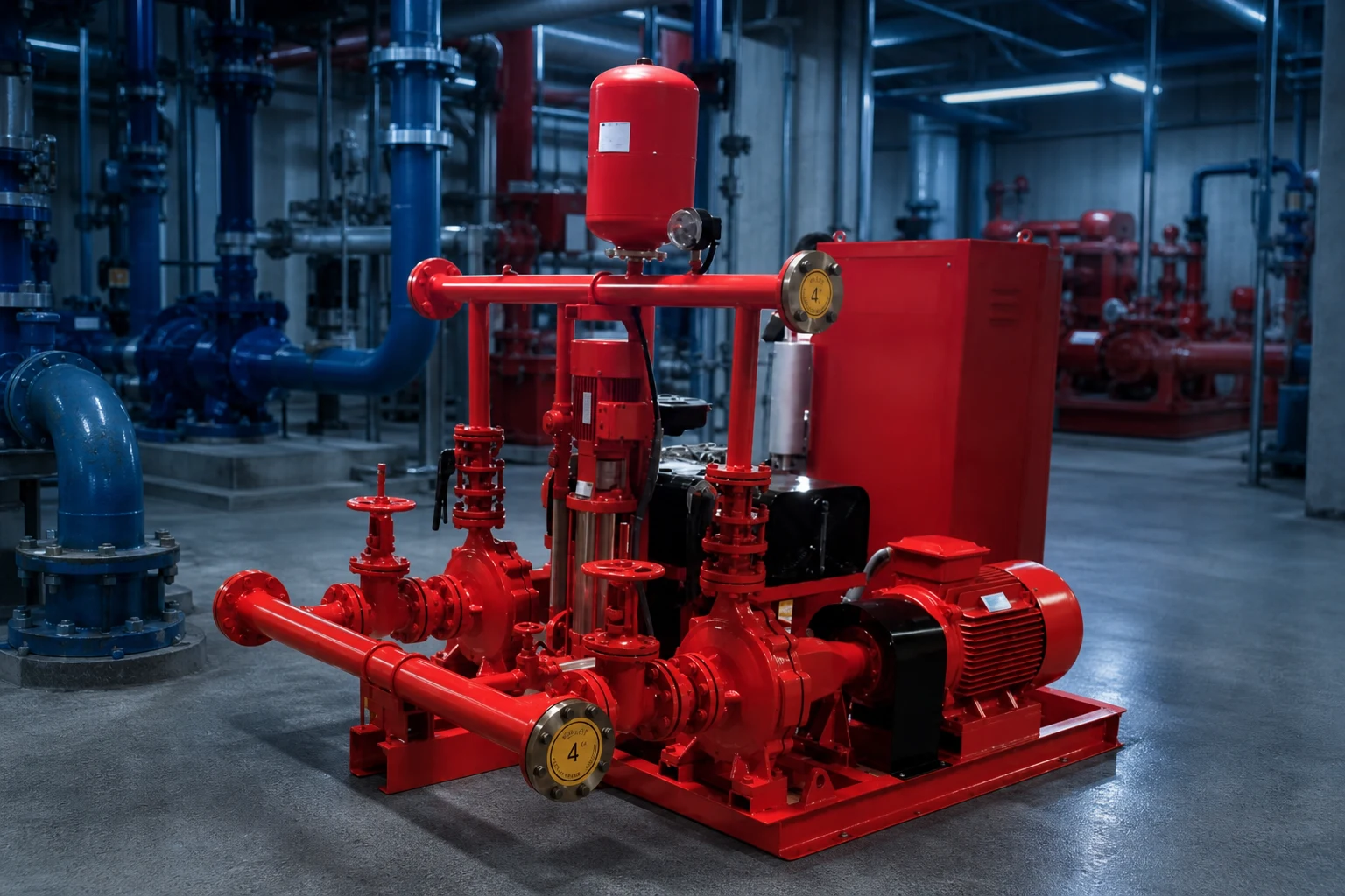
Inspection should look for leakage, corrosion, damage, blocked outlets, closed or improperly positioned valves, missing seals, changed settings, unsafe discharge, freeze exposure, and evidence of repeated operation. Maintenance frequency and test scope follow the adopted requirements, manufacturer instructions, impairment procedure, and facility program. Before isolating or servicing any fire-protection component, follow the approved impairment and notification process. Replacement is not complete until the listing, size, range, setting, discharge, and system record are verified. A relief valve that is silent may still be blocked or isolated, while one that leaks may be warning of system pressure changes. Trend observations with pump test results rather than treating the valve as a standalone plumbing item.
Tedarik ve kabul kaydı
Eksiksiz bir tedarikçi karşılaştırması, ortak bir veri formu kullanmalıdır. Tasarım ve alternatif çalışma noktalarını, akışkan özelliklerini, sıcaklığı, katı maddeleri, tesis rakımını, güç değerini, kumanda sistemini, montaj şeklini, çalışma saatlerini, miktarı, sevk yerini ve istenen belgeleri üst kısma yerleştirin. Fiyat veya verimliliği karşılaştırmadan önce kapsamdaki farklılıkları standardize edin. Sertifikalı eğri veya kapasite verisi, çekilen güç, çalışma limitleri, malzemeler, boyutlar, ağırlık, bağlantılar, motor veya sürücü, kontrol cihazı, aksesuarlar, testler, koruma (konservasyon), yedek parçalar, montaj talimatları ve garanti sınırlarının sunulmasını talep edin. Her bir sapmayı ve çözülmemiş varsayımı kaydedin. Teknik inceleme sırasında, görevin ihtiyaç duymadığı özelliklere puan vermek yerine, sunulan her bir özelliği bir proje girdisiyle eşleştirin. Devreye alma sırasında, kurulan sonucun orijinal temel ile karşılaştırılabilmesi için seçimde kullanılan değişkenlerin aynısını ölçün. Saha koşulları farklılık gösterirse, ekipmanı veya koruma ayarlarını değiştirmeden önce hesaplamayı güncelleyin ve yetkili onayını alın.
Bu konu BORRAPUMP ekipmanıyla nasıl ilişkilidir
Bu kılavuz, şunun erken incelemesini destekler: fire pump relief valve uygulama güzergahı. Son bir model atamaz veya tek bir standart konfigürasyonun her projeye uyduğunu iddia etmez. Önerilen ürünün gerçek hizmete karşı kontrol edilebilmesi için çalışma noktalarını, sıvı verilerini, tesis çizimini, güç kaynağını, kontrolleri, miktarı, varış noktasını, gerekli onayları ve denetim kapsamını gönderin.
İlgili BORRAPUMP mühendislik kılavuzları
- yangın pompası sistemi tasarım temelleri
- NFPA 20 fire pump acceptance testing
- yangın pompası sistem şeması
Yetkili kaynaklar ve ileri düzey öğrenim
NFPA yangın pompaları konusu; OSHA fire protection; FM Global resources. Bu kaynaklar genel güvenlik, çevresel veya mühendislik bağlamı sağlar. Mevcut kabul edilen kurallar, proje onayları ve ekipman talimatları bağlayıcılığını korur.

Practical Engineering'den eğitici video: Pompalar Basınç mı Yoksa Akış mı Oluşturur?. Temel ilkeleri açıklar ve projeye özel talimatların yerini almaz.
Sık sorulan sorular
Kılıf emniyet valfi, ana emniyet valfi ile aynı mıdır?
Hayır. Gövde valfi normalde küçük bir termal tahliye akışı sağlar; ana basınç tahliye valfinin farklı bir sistem basıncı ve kapasite rolü vardır.
Tahliye vanası büyük gelen bir yangın pompasını düzeltebilir mi?
Doğru pompanın, sürücünün ve sistem tasarımının sıradan bir ikamesi olarak kullanılmamalıdır. Onaylı yangından korunma tasarımcısı ve yetkili makam basınç esasını incelemelidir.
Tahliye suyu nereye boşaltılmalıdır?
Onaylı tasarımda gösterilen güvenli, görünür, yönetmeliklere uygun konuma; yeterli drenaj, donma koruması sağlanmış olarak ve ekipman veya insanlar için hiçbir tehlike oluşturmayacak şekilde.
Ayar değiştirmeyi kim yapabilir?
Only qualified authorized personnel following the approved procedure, with calibrated instruments and updated test records.
Final Projesi Kontrol Noktası
Sipariş vermeden veya sahadaki değişiklikten önce, onaylanan çalışma şartlarını ve teknik resimleri tedarikçi verileri, malzemeler, boyutlar, ağırlıklar, bağlantılar, sürücü, kumandalar, aksesuarlar, koruma, test kapsamı, dokümantasyon, yedek parçalar, montaj yöntemi, bakım erişimi ve sevk yeri gereksinimleri ile mutabık hale getirin. Kalan varsayımları kaydedin ve bunların kapatılması için sorumluluk atayın. Son kabul edilen bilgiler, montaj, devreye alma ve gelecekteki bakım için kullanılan aynı temel olmalıdır.