
Size a fire pump suction pipe from the required maximum test and system flow, acceptable velocity and friction loss, the available suction pressure, and the geometry required by the pump and applicable standard. The pipe must deliver water without excessive turbulence, air pockets, or avoidable loss. A diameter chosen only to match the pump nozzle can be too small, while a larger pipe with poor reducers, elbows, or unsupported loads can still cause unreliable suction performance. Keep the calculation and acceptance record with the final project documents so future tests use the same basis.
Keamanan dan cakupan: Pompa pemadam kebakaran dan penggeraknya adalah peralatan keselamatan jiwa. Pekerjaan hidrolik, kelistrikan, diesel, bahan bakar, baterai, tekanan, peralatan berputar, pengujian, dan gangguan harus mengikuti desain disetujui saat ini, instruksi pabrikan, standar yang berlaku, dan otoritas yang memiliki yurisdiksi. Panduan ini menjelaskan jalur keputusan teknik; panduan ini tidak mengizinkan perubahan lapangan, pengoperasian bypass, atau pengoperasian oleh personel yang не berkualifikasi.
- Define the maximum suction flow
- Use continuity to screen velocity
- Calculate suction-side friction
- Protect available suction pressure
- Arrange reducers and fittings carefully
- Keep pipe loads off the pump
- Coordinate tanks and municipal supplies
- Inspect and test the installed route
- Tabel keputusan
- Pertanyaan yang sering diajukan
Define the maximum suction flow
Use the highest flow that the approved pump test or system scenario requires, not only the nominal pump rating. Include simultaneous demand where the design basis requires it. Treat this as a system condition rather than an isolated component choice. Identify the source of every input, the unit used, the operating condition it represents, and the person responsible for approval. If information is preliminary, mark the assumption and test how the decision changes at a conservative boundary. This prevents a neat calculation from hiding an uncertain water level, pressure, valve position, driver condition, or simultaneous demand.
For fire pump suction pipe sizing, verify this section against the selected pump curve, the actual site arrangement, manufacturer instructions, and the current requirements accepted by the authority having jurisdiction. Check the installed condition as well as the drawing because pipe routes, elevations, supports, controls, and access often change during construction. Record the result in a form that can be repeated during commissioning and later inspection. Do not change a safety-critical setting or isolate fire protection without the approved impairment and restoration process.
Use continuity to screen velocity
Calculate velocity from Q divided by pipe area. Treat the result as a screening input, then confirm the current project requirements and the effect of fittings and entrance conditions. The most useful evidence is measured or approved project data, not a copied rule of thumb. Identify the source of every input, the unit used, the operating condition it represents, and the person responsible for approval. If information is preliminary, mark the assumption and test how the decision changes at a conservative boundary. This prevents a neat calculation from hiding an uncertain water level, pressure, valve position, driver condition, or simultaneous demand.
For fire pump suction pipe sizing, verify this section against the selected pump curve, the actual site arrangement, manufacturer instructions, and the current requirements accepted by the authority having jurisdiction. Check the installed condition as well as the drawing because pipe routes, elevations, supports, controls, and access often change during construction. Record the result in a form that can be repeated during commissioning and later inspection. Do not change a safety-critical setting or isolate fire protection without the approved impairment and restoration process.
Calculate suction-side friction
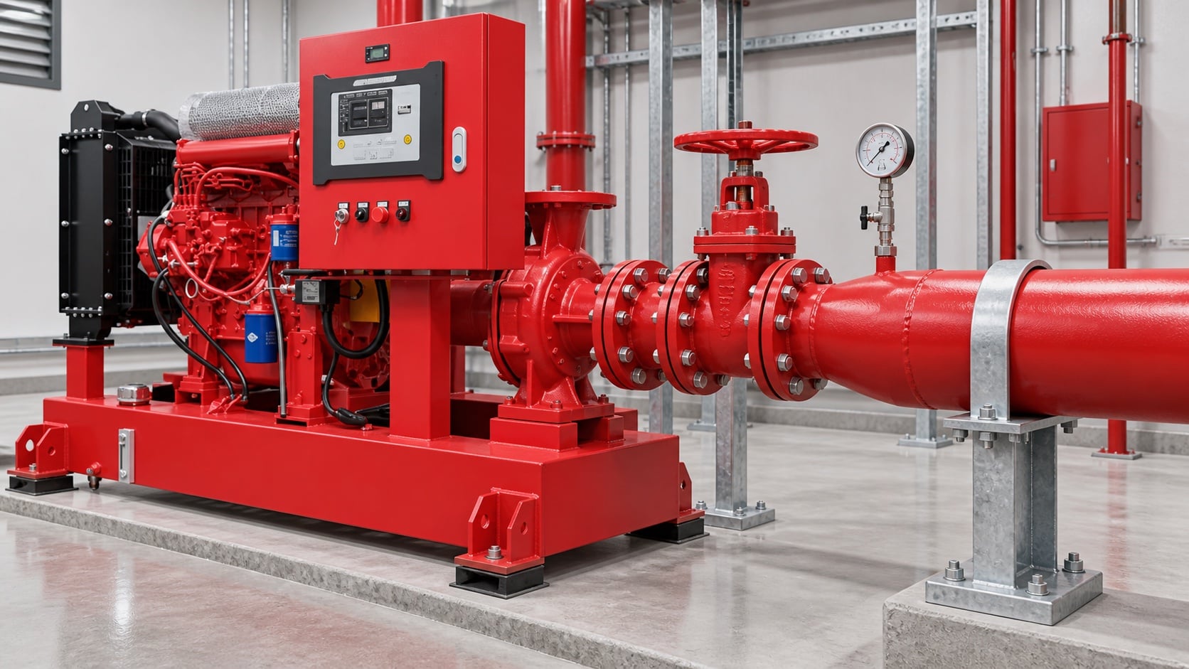
Model pipe length, fittings, valves, strainers where permitted, tank outlet, elevation, and entrance losses. Use the actual internal diameter and appropriate roughness. Review this condition at normal, test, and credible abnormal states before procurement. Identify the source of every input, the unit used, the operating condition it represents, and the person responsible for approval. If information is preliminary, mark the assumption and test how the decision changes at a conservative boundary. This prevents a neat calculation from hiding an uncertain water level, pressure, valve position, driver condition, or simultaneous demand.
For fire pump suction pipe sizing, verify this section against the selected pump curve, the actual site arrangement, manufacturer instructions, and the current requirements accepted by the authority having jurisdiction. Check the installed condition as well as the drawing because pipe routes, elevations, supports, controls, and access often change during construction. Record the result in a form that can be repeated during commissioning and later inspection. Do not change a safety-critical setting or isolate fire protection without the approved impairment and restoration process.
Protect available suction pressure
Combine source level or supply curve with suction loss and vapor-pressure considerations. A positive static level does not guarantee adequate pressure at high flow. The design team should turn this point into a traceable calculation or drawing note. Identify the source of every input, the unit used, the operating condition it represents, and the person responsible for approval. If information is preliminary, mark the assumption and test how the decision changes at a conservative boundary. This prevents a neat calculation from hiding an uncertain water level, pressure, valve position, driver condition, or simultaneous demand.
For fire pump suction pipe sizing, verify this section against the selected pump curve, the actual site arrangement, manufacturer instructions, and the current requirements accepted by the authority having jurisdiction. Check the installed condition as well as the drawing because pipe routes, elevations, supports, controls, and access often change during construction. Record the result in a form that can be repeated during commissioning and later inspection. Do not change a safety-critical setting or isolate fire protection without the approved impairment and restoration process.
Tabel keputusan praktis
| Periksa | Acceptable evidence | Common mistake |
|---|---|---|
| Maximum flow | Approved system and test demand | Using rated flow only |
| Internal diameter | Pipe schedule and measured route | Using nominal size in calculations |
| Fittings | As-built count and geometry | Ignoring entrance and elbow losses |
| Source condition | Low tank level or current supply curve | Using static pressure only |
| Mendukung | Independent support and alignment record | Pulling pipe into the flange |
| Air management | Continuous route without unintended high points | Creating an air pocket |
Arrange reducers and fittings carefully
Use the reducer orientation and straight-run arrangement required for the pump configuration. Avoid high points that trap air and elbows that create distorted flow at the inlet. Treat this as a system condition rather than an isolated component choice. Identify the source of every input, the unit used, the operating condition it represents, and the person responsible for approval. If information is preliminary, mark the assumption and test how the decision changes at a conservative boundary. This prevents a neat calculation from hiding an uncertain water level, pressure, valve position, driver condition, or simultaneous demand.
For fire pump suction pipe sizing, verify this section against the selected pump curve, the actual site arrangement, manufacturer instructions, and the current requirements accepted by the authority having jurisdiction. Check the installed condition as well as the drawing because pipe routes, elevations, supports, controls, and access often change during construction. Record the result in a form that can be repeated during commissioning and later inspection. Do not change a safety-critical setting or isolate fire protection without the approved impairment and restoration process.
Keep pipe loads off the pump
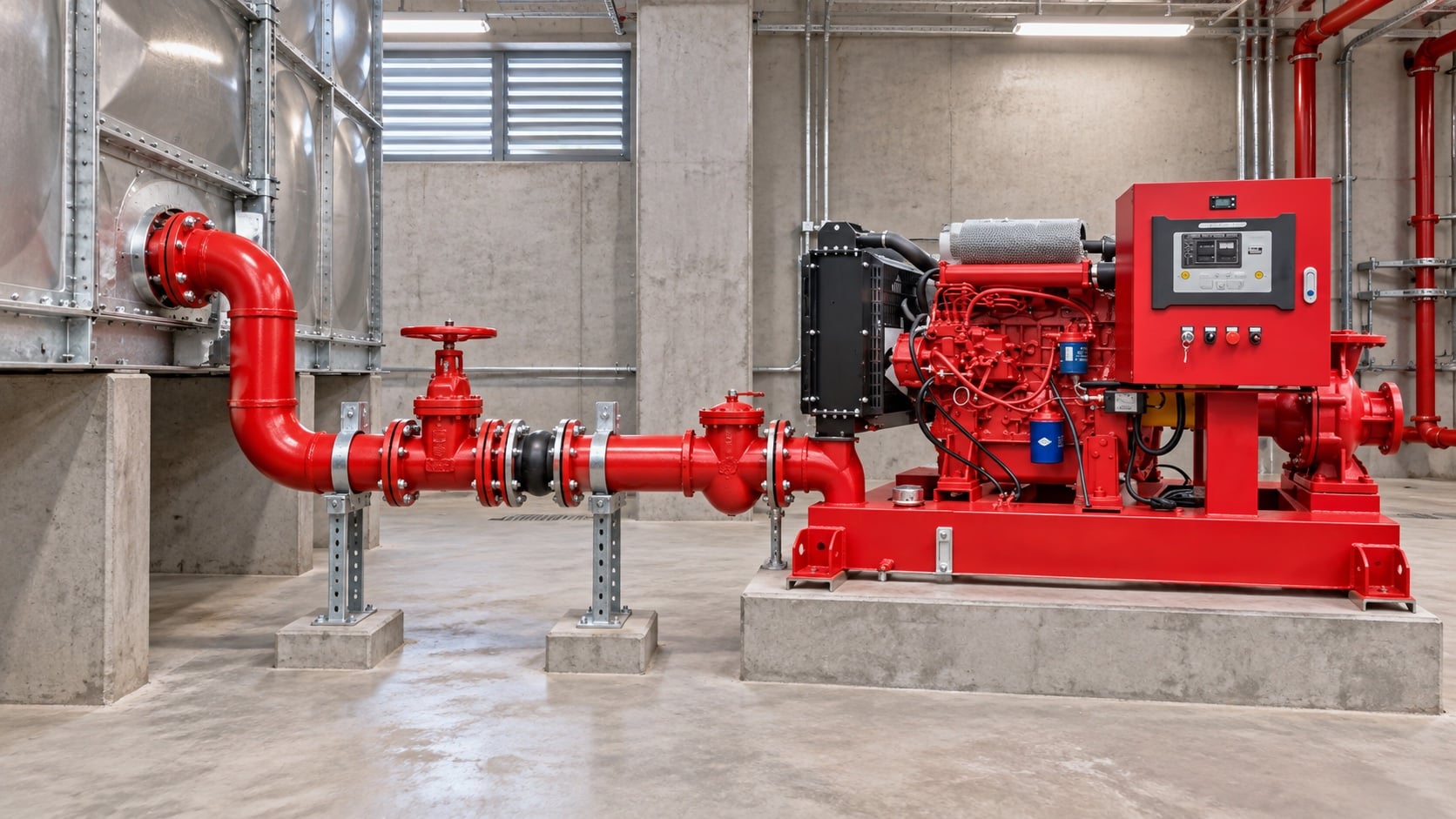
Provide independent supports and verified alignment. The pump nozzle must not carry the weight or thermal movement of the suction pipe. The most useful evidence is measured or approved project data, not a copied rule of thumb. Identify the source of every input, the unit used, the operating condition it represents, and the person responsible for approval. If information is preliminary, mark the assumption and test how the decision changes at a conservative boundary. This prevents a neat calculation from hiding an uncertain water level, pressure, valve position, driver condition, or simultaneous demand.
For fire pump suction pipe sizing, verify this section against the selected pump curve, the actual site arrangement, manufacturer instructions, and the current requirements accepted by the authority having jurisdiction. Check the installed condition as well as the drawing because pipe routes, elevations, supports, controls, and access often change during construction. Record the result in a form that can be repeated during commissioning and later inspection. Do not change a safety-critical setting or isolate fire protection without the approved impairment and restoration process.
Coordinate tanks and municipal supplies
For tanks, confirm usable low-water level and outlet behavior. For mains, use a current supply test and consider the lowest credible available pressure. Review this condition at normal, test, and credible abnormal states before procurement. Identify the source of every input, the unit used, the operating condition it represents, and the person responsible for approval. If information is preliminary, mark the assumption and test how the decision changes at a conservative boundary. This prevents a neat calculation from hiding an uncertain water level, pressure, valve position, driver condition, or simultaneous demand.
For fire pump suction pipe sizing, verify this section against the selected pump curve, the actual site arrangement, manufacturer instructions, and the current requirements accepted by the authority having jurisdiction. Check the installed condition as well as the drawing because pipe routes, elevations, supports, controls, and access often change during construction. Record the result in a form that can be repeated during commissioning and later inspection. Do not change a safety-critical setting or isolate fire protection without the approved impairment and restoration process.
Inspect and test the installed route
Compare as-built pipe with drawings, verify valve position and accessibility, flush debris, then record suction pressure across the required flow range. The design team should turn this point into a traceable calculation or drawing note. Identify the source of every input, the unit used, the operating condition it represents, and the person responsible for approval. If information is preliminary, mark the assumption and test how the decision changes at a conservative boundary. This prevents a neat calculation from hiding an uncertain water level, pressure, valve position, driver condition, or simultaneous demand.
For fire pump suction pipe sizing, verify this section against the selected pump curve, the actual site arrangement, manufacturer instructions, and the current requirements accepted by the authority having jurisdiction. Check the installed condition as well as the drawing because pipe routes, elevations, supports, controls, and access often change during construction. Record the result in a form that can be repeated during commissioning and later inspection. Do not change a safety-critical setting or isolate fire protection without the approved impairment and restoration process.
Bagaimana ini terkait dengan peralatan BORRAPUMP
BORRAPUMP memasok peralatan pompa rekayasa untuk proyek-proyek air dan proteksi kebakaran. Tinjau yang relevan Konfigurasi produk BORRAPUMP sebagai titik awal, lalu serahkan aliran, tinggi tekan, sumber air, penggerak, daya, kontrol, kondisi lokasi, persyaratan yang berlaku, jumlah, dan tujuan yang diperlukan. Pemilihan akhir harus menggunakan dasar hidrolik proyek dan submittal yang disetujui; panduan ini tidak mengklaim bahwa satu susunan katalog cocok untuk setiap yurisdiksi atau risiko.
Panduan BORRAPUMP terkait
- pompa pemadam kebakaran diesel versus elektrik
- pemilihan paket pompa pemadam kebakaran
- Panduan pengujian penerimaan NFPA 20
Referensi otoritatif
Sumber-sumber berikut menetapkan batas standar, konteks keselamatan kebakaran, dan prinsip sistem pompa yang digunakan dalam panduan ini. Selalu terapkan edisi dan adopsi lokal yang disetujui untuk proyek tersebut.
- Halaman pengembangan standar NFPA 20
- Sumber daya sistem pompa Departemen Energi AS
- penelitian perlindungan kebakaran NIST
Video edukasi

Latar belakang pendidikan oleh Practical Engineering: Apakah Pompa Menghasilkan Tekanan atau Aliran?. Video tersebut mendukung konsep teknik yang mendasar dan tidak menggantikan persyaratan perlindungan kebakaran khusus proyek.
Pertanyaan yang sering diajukan
Bisakah pipa hisap sama dengan ukuran saluran masuk pompa?
Tidak otomatis. Periksa aliran, kecepatan, rugi-rugi, tekanan yang tersedia, dan aturan instalasi yang berlaku yang diperlukan.
Mengapa siku di dekat saluran masuk menjadi perhatian?
Hal ini dapat menimbulkan kecepatan yang tidak merata dan pusaran air di saluran masuk pompa. Patuhi persyaratan penataan pompa dan proyek.
Apakah saya harus menyertakan alur pengujian saat melakukan *sizing*?
Ya, evaluasi aliran tertinggi yang diperlukan selama pengujian dan operasi yang disetujui.
Apakah ketinggian tangki yang positif sudah cukup untuk mencegah kavitasi?
Tidak. Tekanan yang tersedia juga bergantung pada kerugian, suhu, tekanan atmosfer, dan kebutuhan pompa.
Daftar periksa verifikasi akhir
Sebelum persetujuan, konfirmasikan basis hidrolik, kondisi sumber air, kurva pompa yang dipilih, data penggerak dan pengontrol, peringkat tekanan komponen, susunan katup, metode pengujian, akses, drainase, alarm, dan prosedur pemulihan. Selesaikan perbedaan antara gambar kerja dan sistem yang terpasang. Selama pengujian (commissioning), gunakan instrumen yang dikalibrasi dan catat tekanan isap, tekanan buang, aliran, kecepatan, kondisi penggerak, alarm, dan pengamatan tidak normal pada setiap titik yang diperlukan. Simpan hasil yang diterima bersama catatan ruang pompa sehingga pemeriksaan selanjutnya dapat membandingkan hal yang setara.