
Size a fire pump suction pipe from the required maximum test and system flow, acceptable velocity and friction loss, the available suction pressure, and the geometry required by the pump and applicable standard. The pipe must deliver water without excessive turbulence, air pockets, or avoidable loss. A diameter chosen only to match the pump nozzle can be too small, while a larger pipe with poor reducers, elbows, or unsupported loads can still cause unreliable suction performance. Keep the calculation and acceptance record with the final project documents so future tests use the same basis.
Segurança e âmbito: As bombas de incêndio e respetivos acionadores são equipamento de segurança de vida. Os trabalhos hidráulicos, elétricos, a diesel, de combustível, de bateria, de pressão, de equipamento rotativo, de ensaio e de anomalias devem seguir o projeto aprovado em vigor, as instruções do fabricante, as normas aplicáveis e a autoridade com jurisdição. Este guia explica o caminho de decisão de engenharia; não autoriza alterações em campo, desvios ou a operação por pessoal não qualificado.
- Define the maximum suction flow
- Use continuity to screen velocity
- Calculate suction-side friction
- Protect available suction pressure
- Arrange reducers and fittings carefully
- Keep pipe loads off the pump
- Coordinate tanks and municipal supplies
- Inspect and test the installed route
- tabela de decisão
- Perguntas frequentes
Define the maximum suction flow
Use the highest flow that the approved pump test or system scenario requires, not only the nominal pump rating. Include simultaneous demand where the design basis requires it. Treat this as a system condition rather than an isolated component choice. Identify the source of every input, the unit used, the operating condition it represents, and the person responsible for approval. If information is preliminary, mark the assumption and test how the decision changes at a conservative boundary. This prevents a neat calculation from hiding an uncertain water level, pressure, valve position, driver condition, or simultaneous demand.
For fire pump suction pipe sizing, verify this section against the selected pump curve, the actual site arrangement, manufacturer instructions, and the current requirements accepted by the authority having jurisdiction. Check the installed condition as well as the drawing because pipe routes, elevations, supports, controls, and access often change during construction. Record the result in a form that can be repeated during commissioning and later inspection. Do not change a safety-critical setting or isolate fire protection without the approved impairment and restoration process.
Use continuity to screen velocity
Calculate velocity from Q divided by pipe area. Treat the result as a screening input, then confirm the current project requirements and the effect of fittings and entrance conditions. The most useful evidence is measured or approved project data, not a copied rule of thumb. Identify the source of every input, the unit used, the operating condition it represents, and the person responsible for approval. If information is preliminary, mark the assumption and test how the decision changes at a conservative boundary. This prevents a neat calculation from hiding an uncertain water level, pressure, valve position, driver condition, or simultaneous demand.
For fire pump suction pipe sizing, verify this section against the selected pump curve, the actual site arrangement, manufacturer instructions, and the current requirements accepted by the authority having jurisdiction. Check the installed condition as well as the drawing because pipe routes, elevations, supports, controls, and access often change during construction. Record the result in a form that can be repeated during commissioning and later inspection. Do not change a safety-critical setting or isolate fire protection without the approved impairment and restoration process.
Calculate suction-side friction
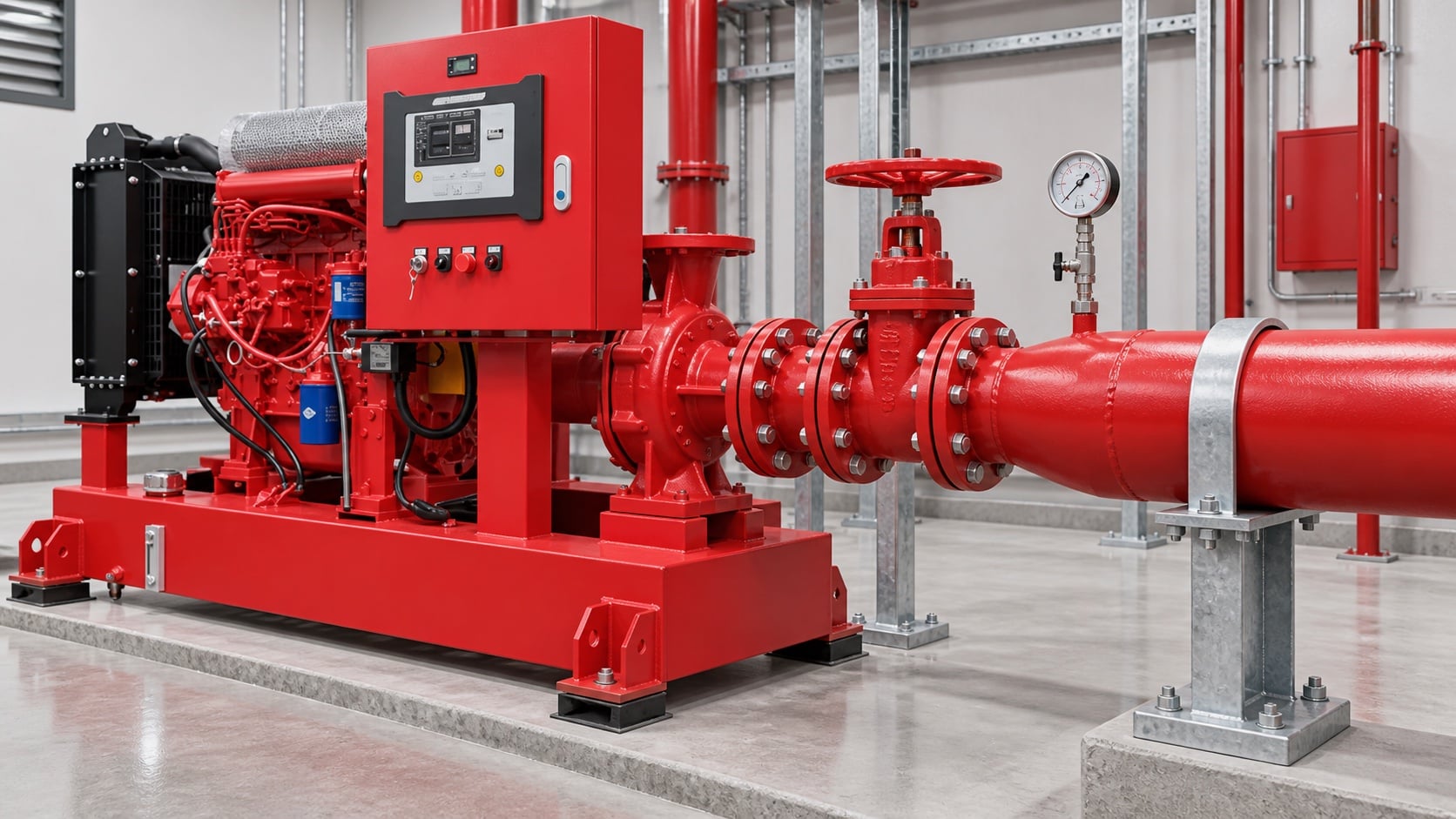
Model pipe length, fittings, valves, strainers where permitted, tank outlet, elevation, and entrance losses. Use the actual internal diameter and appropriate roughness. Review this condition at normal, test, and credible abnormal states before procurement. Identify the source of every input, the unit used, the operating condition it represents, and the person responsible for approval. If information is preliminary, mark the assumption and test how the decision changes at a conservative boundary. This prevents a neat calculation from hiding an uncertain water level, pressure, valve position, driver condition, or simultaneous demand.
For fire pump suction pipe sizing, verify this section against the selected pump curve, the actual site arrangement, manufacturer instructions, and the current requirements accepted by the authority having jurisdiction. Check the installed condition as well as the drawing because pipe routes, elevations, supports, controls, and access often change during construction. Record the result in a form that can be repeated during commissioning and later inspection. Do not change a safety-critical setting or isolate fire protection without the approved impairment and restoration process.
Protect available suction pressure
Combine source level or supply curve with suction loss and vapor-pressure considerations. A positive static level does not guarantee adequate pressure at high flow. The design team should turn this point into a traceable calculation or drawing note. Identify the source of every input, the unit used, the operating condition it represents, and the person responsible for approval. If information is preliminary, mark the assumption and test how the decision changes at a conservative boundary. This prevents a neat calculation from hiding an uncertain water level, pressure, valve position, driver condition, or simultaneous demand.
For fire pump suction pipe sizing, verify this section against the selected pump curve, the actual site arrangement, manufacturer instructions, and the current requirements accepted by the authority having jurisdiction. Check the installed condition as well as the drawing because pipe routes, elevations, supports, controls, and access often change during construction. Record the result in a form that can be repeated during commissioning and later inspection. Do not change a safety-critical setting or isolate fire protection without the approved impairment and restoration process.
Tabela de decisão prática
| Verificar | Acceptable evidence | Common mistake |
|---|---|---|
| Maximum flow | Approved system and test demand | Using rated flow only |
| Internal diameter | Pipe schedule and measured route | Using nominal size in calculations |
| Fittings | As-built count and geometry | Ignoring entrance and elbow losses |
| Source condition | Low tank level or current supply curve | Using static pressure only |
| Apoios | Independent support and alignment record | Pulling pipe into the flange |
| Air management | Continuous route without unintended high points | Creating an air pocket |
Arrange reducers and fittings carefully
Use the reducer orientation and straight-run arrangement required for the pump configuration. Avoid high points that trap air and elbows that create distorted flow at the inlet. Treat this as a system condition rather than an isolated component choice. Identify the source of every input, the unit used, the operating condition it represents, and the person responsible for approval. If information is preliminary, mark the assumption and test how the decision changes at a conservative boundary. This prevents a neat calculation from hiding an uncertain water level, pressure, valve position, driver condition, or simultaneous demand.
For fire pump suction pipe sizing, verify this section against the selected pump curve, the actual site arrangement, manufacturer instructions, and the current requirements accepted by the authority having jurisdiction. Check the installed condition as well as the drawing because pipe routes, elevations, supports, controls, and access often change during construction. Record the result in a form that can be repeated during commissioning and later inspection. Do not change a safety-critical setting or isolate fire protection without the approved impairment and restoration process.
Keep pipe loads off the pump
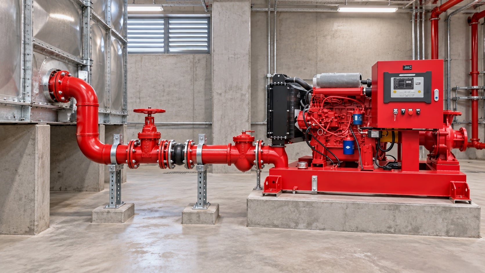
Provide independent supports and verified alignment. The pump nozzle must not carry the weight or thermal movement of the suction pipe. The most useful evidence is measured or approved project data, not a copied rule of thumb. Identify the source of every input, the unit used, the operating condition it represents, and the person responsible for approval. If information is preliminary, mark the assumption and test how the decision changes at a conservative boundary. This prevents a neat calculation from hiding an uncertain water level, pressure, valve position, driver condition, or simultaneous demand.
For fire pump suction pipe sizing, verify this section against the selected pump curve, the actual site arrangement, manufacturer instructions, and the current requirements accepted by the authority having jurisdiction. Check the installed condition as well as the drawing because pipe routes, elevations, supports, controls, and access often change during construction. Record the result in a form that can be repeated during commissioning and later inspection. Do not change a safety-critical setting or isolate fire protection without the approved impairment and restoration process.
Coordinate tanks and municipal supplies
For tanks, confirm usable low-water level and outlet behavior. For mains, use a current supply test and consider the lowest credible available pressure. Review this condition at normal, test, and credible abnormal states before procurement. Identify the source of every input, the unit used, the operating condition it represents, and the person responsible for approval. If information is preliminary, mark the assumption and test how the decision changes at a conservative boundary. This prevents a neat calculation from hiding an uncertain water level, pressure, valve position, driver condition, or simultaneous demand.
For fire pump suction pipe sizing, verify this section against the selected pump curve, the actual site arrangement, manufacturer instructions, and the current requirements accepted by the authority having jurisdiction. Check the installed condition as well as the drawing because pipe routes, elevations, supports, controls, and access often change during construction. Record the result in a form that can be repeated during commissioning and later inspection. Do not change a safety-critical setting or isolate fire protection without the approved impairment and restoration process.
Inspect and test the installed route
Compare as-built pipe with drawings, verify valve position and accessibility, flush debris, then record suction pressure across the required flow range. The design team should turn this point into a traceable calculation or drawing note. Identify the source of every input, the unit used, the operating condition it represents, and the person responsible for approval. If information is preliminary, mark the assumption and test how the decision changes at a conservative boundary. This prevents a neat calculation from hiding an uncertain water level, pressure, valve position, driver condition, or simultaneous demand.
For fire pump suction pipe sizing, verify this section against the selected pump curve, the actual site arrangement, manufacturer instructions, and the current requirements accepted by the authority having jurisdiction. Check the installed condition as well as the drawing because pipe routes, elevations, supports, controls, and access often change during construction. Record the result in a form that can be repeated during commissioning and later inspection. Do not change a safety-critical setting or isolate fire protection without the approved impairment and restoration process.
Como isto se relaciona com o equipamento BORRAPUMP
A BORRAPUMP fornece equipamento de bombagem concebido por engenharia para projetos de água e proteção contra incêndios. Reveja o relevante Configuração do produto BORRAPUMP como ponto de partida, submeta seguidamente o caudal, a altura manométria, a fonte de água, o acionador, a potência, os controlos, as condições do local, os requisitos aplicáveis, a quantidade e o destino. A seleção final deve utilizar a base hidráulica do projeto e a submissão aprovada; este guia não afirma que uma disposição de catálogo se adapta a todas as jurisdições ou riscos.
Guias BORRAPUMP relacionados
- bombas de incêndio a gasóleo versus elétricas
- seleção do grupo gerador de incêndio
- guia de testes de aceitação da NFPA 20
Referências fidedignas
As fontes seguintes estabelecem os limites normativos, o contexto de segurança contra incêndios e os princípios dos sistemas de bombagem utilizados neste guia. Aplique sempre a edição e a adoção local aceites para o projeto.
- Página de desenvolvimento da norma NFPA 20
- Recursos de sistemas de bombagem do Departamento de Energia dos EUA
- investigação sobre protecção contra incêndios do NIST
Vídeo educativo

Formação académica por Practical Engineering: As bombas criam pressão ou caudal?. O vídeo apoia o conceito de engenharia subjacente e não substitui os requisitos de proteção contra incêndio específicos do projeto.
Perguntas frequentes
Pode o tubo de aspiração ser igual ao tamanho da entrada da bomba?
Não automaticamente. Verifique o caudal, a velocidade, a perda de carga, a pressão disponível e as regras de instalação aplicáveis.
Por que razão é que um cotovelo perto da entrada é motivo de preocupação?
Pode criar velocidade irregular e turbulência na entrada da bomba. Siga os requisitos de disposição da bomba e do projeto.
Incluo o fluxo de teste no dimensionamento?
Sim, avaliar o caudal mais elevado exigido durante os ensaios e a operação aprovados.
Um nível positivo no depósito é suficiente para evitar a cavitação?
No. Available pressure also depends on losses, temperature, atmospheric pressure, and the pump requirement.
Lista de verificação de verificação final
Antes da aprovação, confirme a base hidráulica, a condição da captação de água, a curva da bomba selecionada, os dados do acionador e do controlador, as pressões nominais dos componentes, o arranjo das válvulas, o método de ensaio, o acesso, a drenagem, os alarmes e o procedimento de restabelecimento. Resolva as divergências entre os desenhos e o sistema instalado. Durante a comissão, utilize instrumentos calibrados e registe a pressão de aspiração, a pressão de descarga, o caudal, a velocidade, a condição do acionador, os alarmes e as observações anómalas em cada ponto necessário. Mantenha os resultados aceites junto dos registos da casa de bombas para que inspeções posteriores comparem dados equivalentes.