
Size a fire pump suction pipe from the required maximum test and system flow, acceptable velocity and friction loss, the available suction pressure, and the geometry required by the pump and applicable standard. The pipe must deliver water without excessive turbulence, air pockets, or avoidable loss. A diameter chosen only to match the pump nozzle can be too small, while a larger pipe with poor reducers, elbows, or unsupported loads can still cause unreliable suction performance. Keep the calculation and acceptance record with the final project documents so future tests use the same basis.
السلام والنشاط: مضخات الحريق ومحركاتها هي معدات للسلامة في الحياة. يجب أن تتوافق أعمال الأنظمة الهيدروليكية، والكهربائية، والديزل، والوقود، والبطاريات، والضغط، والمعدات الدوارة، والاختبار، وتعطيل الأنظمة مع التصميم الحالي المعتمد، وتتعليمات الشركة المصنعة، والمعايير المطبقة، والجهة المختصة ذات الصلاحية. يوضح هذا الدليل مسار القرار الهندسي؛ ولا يمنح الإذن بإجراء تعديلات ميدانية، أو تجاوزات، أو تشغيل بواسطة أشخاص غير مؤهلين.
- Define the maximum suction flow
- Use continuity to screen velocity
- Calculate suction-side friction
- Protect available suction pressure
- Arrange reducers and fittings carefully
- Keep pipe loads off the pump
- Coordinate tanks and municipal supplies
- Inspect and test the installed route
- جدول القرار
- الأسئلة الشائعة
Define the maximum suction flow
Use the highest flow that the approved pump test or system scenario requires, not only the nominal pump rating. Include simultaneous demand where the design basis requires it. Treat this as a system condition rather than an isolated component choice. Identify the source of every input, the unit used, the operating condition it represents, and the person responsible for approval. If information is preliminary, mark the assumption and test how the decision changes at a conservative boundary. This prevents a neat calculation from hiding an uncertain water level, pressure, valve position, driver condition, or simultaneous demand.
For fire pump suction pipe sizing, verify this section against the selected pump curve, the actual site arrangement, manufacturer instructions, and the current requirements accepted by the authority having jurisdiction. Check the installed condition as well as the drawing because pipe routes, elevations, supports, controls, and access often change during construction. Record the result in a form that can be repeated during commissioning and later inspection. Do not change a safety-critical setting or isolate fire protection without the approved impairment and restoration process.
Use continuity to screen velocity
Calculate velocity from Q divided by pipe area. Treat the result as a screening input, then confirm the current project requirements and the effect of fittings and entrance conditions. The most useful evidence is measured or approved project data, not a copied rule of thumb. Identify the source of every input, the unit used, the operating condition it represents, and the person responsible for approval. If information is preliminary, mark the assumption and test how the decision changes at a conservative boundary. This prevents a neat calculation from hiding an uncertain water level, pressure, valve position, driver condition, or simultaneous demand.
For fire pump suction pipe sizing, verify this section against the selected pump curve, the actual site arrangement, manufacturer instructions, and the current requirements accepted by the authority having jurisdiction. Check the installed condition as well as the drawing because pipe routes, elevations, supports, controls, and access often change during construction. Record the result in a form that can be repeated during commissioning and later inspection. Do not change a safety-critical setting or isolate fire protection without the approved impairment and restoration process.
Calculate suction-side friction
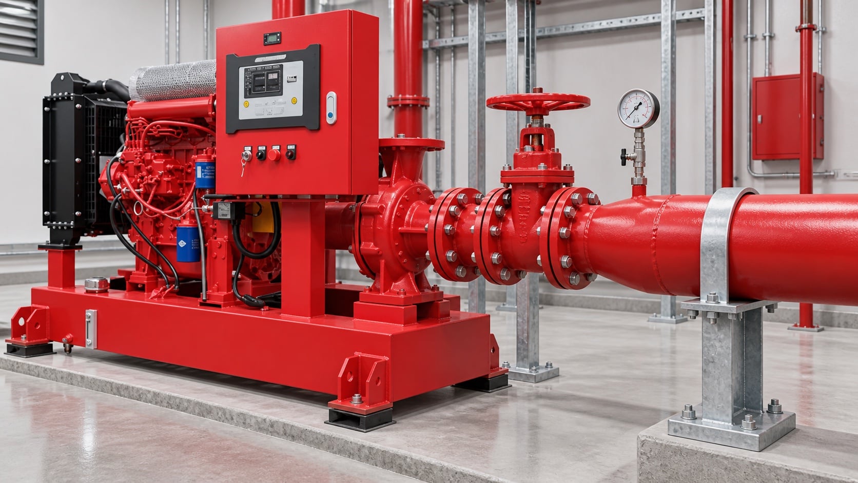
Model pipe length, fittings, valves, strainers where permitted, tank outlet, elevation, and entrance losses. Use the actual internal diameter and appropriate roughness. Review this condition at normal, test, and credible abnormal states before procurement. Identify the source of every input, the unit used, the operating condition it represents, and the person responsible for approval. If information is preliminary, mark the assumption and test how the decision changes at a conservative boundary. This prevents a neat calculation from hiding an uncertain water level, pressure, valve position, driver condition, or simultaneous demand.
For fire pump suction pipe sizing, verify this section against the selected pump curve, the actual site arrangement, manufacturer instructions, and the current requirements accepted by the authority having jurisdiction. Check the installed condition as well as the drawing because pipe routes, elevations, supports, controls, and access often change during construction. Record the result in a form that can be repeated during commissioning and later inspection. Do not change a safety-critical setting or isolate fire protection without the approved impairment and restoration process.
Protect available suction pressure
Combine source level or supply curve with suction loss and vapor-pressure considerations. A positive static level does not guarantee adequate pressure at high flow. The design team should turn this point into a traceable calculation or drawing note. Identify the source of every input, the unit used, the operating condition it represents, and the person responsible for approval. If information is preliminary, mark the assumption and test how the decision changes at a conservative boundary. This prevents a neat calculation from hiding an uncertain water level, pressure, valve position, driver condition, or simultaneous demand.
For fire pump suction pipe sizing, verify this section against the selected pump curve, the actual site arrangement, manufacturer instructions, and the current requirements accepted by the authority having jurisdiction. Check the installed condition as well as the drawing because pipe routes, elevations, supports, controls, and access often change during construction. Record the result in a form that can be repeated during commissioning and later inspection. Do not change a safety-critical setting or isolate fire protection without the approved impairment and restoration process.
جدول قرارات عملي
| تحقق | Acceptable evidence | خطأ شائع |
|---|---|---|
| Maximum flow | Approved system and test demand | Using rated flow only |
| Internal diameter | Pipe schedule and measured route | Using nominal size in calculations |
| Fittings | As-built count and geometry | Ignoring entrance and elbow losses |
| Source condition | Low tank level or current supply curve | Using static pressure only |
| يدعم | Independent support and alignment record | Pulling pipe into the flange |
| Air management | Continuous route without unintended high points | Creating an air pocket |
Arrange reducers and fittings carefully
Use the reducer orientation and straight-run arrangement required for the pump configuration. Avoid high points that trap air and elbows that create distorted flow at the inlet. Treat this as a system condition rather than an isolated component choice. Identify the source of every input, the unit used, the operating condition it represents, and the person responsible for approval. If information is preliminary, mark the assumption and test how the decision changes at a conservative boundary. This prevents a neat calculation from hiding an uncertain water level, pressure, valve position, driver condition, or simultaneous demand.
For fire pump suction pipe sizing, verify this section against the selected pump curve, the actual site arrangement, manufacturer instructions, and the current requirements accepted by the authority having jurisdiction. Check the installed condition as well as the drawing because pipe routes, elevations, supports, controls, and access often change during construction. Record the result in a form that can be repeated during commissioning and later inspection. Do not change a safety-critical setting or isolate fire protection without the approved impairment and restoration process.
Keep pipe loads off the pump
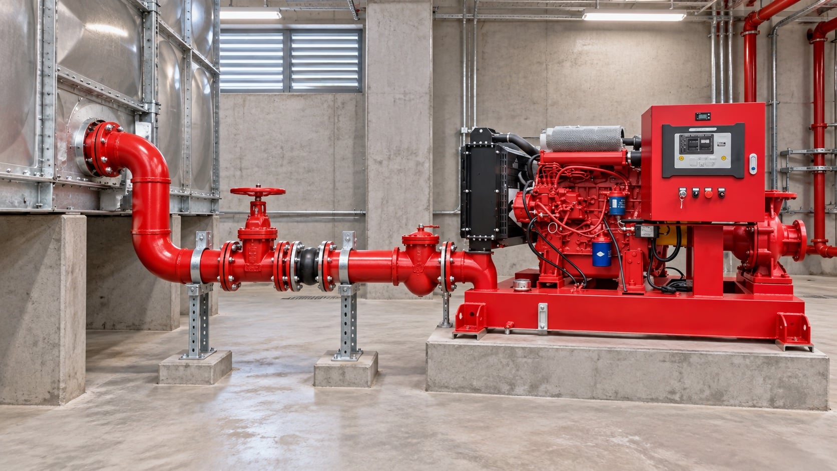
Provide independent supports and verified alignment. The pump nozzle must not carry the weight or thermal movement of the suction pipe. The most useful evidence is measured or approved project data, not a copied rule of thumb. Identify the source of every input, the unit used, the operating condition it represents, and the person responsible for approval. If information is preliminary, mark the assumption and test how the decision changes at a conservative boundary. This prevents a neat calculation from hiding an uncertain water level, pressure, valve position, driver condition, or simultaneous demand.
For fire pump suction pipe sizing, verify this section against the selected pump curve, the actual site arrangement, manufacturer instructions, and the current requirements accepted by the authority having jurisdiction. Check the installed condition as well as the drawing because pipe routes, elevations, supports, controls, and access often change during construction. Record the result in a form that can be repeated during commissioning and later inspection. Do not change a safety-critical setting or isolate fire protection without the approved impairment and restoration process.
Coordinate tanks and municipal supplies
For tanks, confirm usable low-water level and outlet behavior. For mains, use a current supply test and consider the lowest credible available pressure. Review this condition at normal, test, and credible abnormal states before procurement. Identify the source of every input, the unit used, the operating condition it represents, and the person responsible for approval. If information is preliminary, mark the assumption and test how the decision changes at a conservative boundary. This prevents a neat calculation from hiding an uncertain water level, pressure, valve position, driver condition, or simultaneous demand.
For fire pump suction pipe sizing, verify this section against the selected pump curve, the actual site arrangement, manufacturer instructions, and the current requirements accepted by the authority having jurisdiction. Check the installed condition as well as the drawing because pipe routes, elevations, supports, controls, and access often change during construction. Record the result in a form that can be repeated during commissioning and later inspection. Do not change a safety-critical setting or isolate fire protection without the approved impairment and restoration process.
Inspect and test the installed route
Compare as-built pipe with drawings, verify valve position and accessibility, flush debris, then record suction pressure across the required flow range. The design team should turn this point into a traceable calculation or drawing note. Identify the source of every input, the unit used, the operating condition it represents, and the person responsible for approval. If information is preliminary, mark the assumption and test how the decision changes at a conservative boundary. This prevents a neat calculation from hiding an uncertain water level, pressure, valve position, driver condition, or simultaneous demand.
For fire pump suction pipe sizing, verify this section against the selected pump curve, the actual site arrangement, manufacturer instructions, and the current requirements accepted by the authority having jurisdiction. Check the installed condition as well as the drawing because pipe routes, elevations, supports, controls, and access often change during construction. Record the result in a form that can be repeated during commissioning and later inspection. Do not change a safety-critical setting or isolate fire protection without the approved impairment and restoration process.
كيف يرتبط هذا بمعدات BORRAPUMP
توفر شركة BORRAPUMP معدات ضخ هندسية لمشاريع المياه والحماية من الحريق. راجع ما يخص ذلك تكوين منتج BORRAPUMP كمنطلق، ثم قم بتقديم التدفق المطلوب، والرأس، ومصدر المياه، والمشغل، والطاقة، وأدوات التحكم، وظروف الموقع، والمتطلبات المطبقة، والكمية، والوجهة. يجب أن يستخدم الاختيار النهائي الأساس الهيدروليكي للمشروع والتقديم المعتمد؛ لا يدعي هذا الدليل أن ترتيباً واحداً في الكتالوج يناسب كل اختصاص أو مخاطرة.
أدلة BORRAPUMP ذات الصلة
- مضخات الحريق التي تعمل بالديزل مقابل الكهرباء
- اختيار منظومة مضخات الحريق
- دليل اختبار قبول المعيار NFPA 20
مراجع موثوقة
تحدد المصادر التالية حدود المعايير، وسياق السلامة من الحرائق، ومبادئ نظام المضخات المستخدمة في هذا الدليل. قم دائماً بتطبيق الإصدار والاعتماد المحلي المقبول للمشروع.
- صفحة تطوير معيار NFPA 20
- موارد أنظمة المضخات التابعة لوزارة الطاقة الأمريكية
- أبحاث المعهد الوطني للمعايير والتقنية (نيست) للحماية من الحريق
فيديو تعليمي

الخلفية التعليمية بواسطة الهندسة العملية: هل المضخات تولد ضغطاً أم تدفقاً؟. يدعم الفيديو مفهوم الهندسة الأساسي ولا يحل محل متطلبات الحماية من الحريق الخاصة بالمشروع.
الأسئلة الشائعة
هل يمكن أن يتساوى حجم أنبوب الشحب مع حجم مدخل المضخة؟
ليس تلقائياً. تحقق من التدفق المطلوب، والسرعة، والفقد، والضغط المتاح، وقواعد التركيب المطبقة.
لماذا يُعدّ المرفق (الكوع) القريب من المدخل مصدر قلق؟
يمكن أن يتسبب ذلك في عدم انتظام السرعة والدوامة عند مدخل المضخة. اتبع متطلبات ترتيب المضخة والمشروع.
هل تتضمن تدفق الاختبار عند التقدير؟
نعم، تقييم أعلى تدفق مطلوب أثناء الاختبار والتشغيل المعتمدين.
هل مستوى الخزان الموجب كافٍ لمنع التكاثر (أو التكهف)؟
No. Available pressure also depends on losses, temperature, atmospheric pressure, and the pump requirement.
قائمة التحقق من التحقق النهائي
قبل الموافقة، قم بتأكيد الأساس الهيدروليكي، وحالة مصدر المياه، ومنحنى المضخة المختار، وبيانات المحرك ووحدة التحكم، وتصنيفات ضغط المكونات، وترتيب الصمامات، وطريقة الاختبار، وسُبل الوصول، والصرف، والإنذارات، وإجراءات إعادة التشغيل. قم بحل أي اختلافات بين المخططات والنظام المُركَّب. وأثناء التشغيل التجريبي، استخدم أدوات معايرة وسجّل ضغط السحب، وضغط الطرد، ومعدل التدفق، والسرعة، وحالة المحرك، والإنذارات، والملاحظات غير الطبيعية عند كل نقطة مطلوبة. احتفظ بالنتائج المقبولة مع سجلات غرفة المضخات لكي تُقارن عمليات الفحص اللاحقة النتائج المتشابهة ببعضها.