
Size a fire pump suction pipe from the required maximum test and system flow, acceptable velocity and friction loss, the available suction pressure, and the geometry required by the pump and applicable standard. The pipe must deliver water without excessive turbulence, air pockets, or avoidable loss. A diameter chosen only to match the pump nozzle can be too small, while a larger pipe with poor reducers, elbows, or unsupported loads can still cause unreliable suction performance. Keep the calculation and acceptance record with the final project documents so future tests use the same basis.
Güvenlik ve kapsam: Yangın pompaları ve tahrik üniteleri can güvenliği ekipmanıdır. Hidrolik, elektriksel, dizel, yakıt, akü, basınç, döner ekipman, test ve arıza/devre dışı bırakma çalışmaları; yürürlükteki onaylı tasarıma, üretici talimatlarına, geçerli standartlara ve yetkili merciye uygun olmalıdır. Bu kılavuz mühendislik karar yolunu açıklar; saha değişikliklerini, bypass işlemlerini veya yetkisiz personel tarafından çalıştırılmayı yetkilendirmez.
- Define the maximum suction flow
- Use continuity to screen velocity
- Calculate suction-side friction
- Protect available suction pressure
- Arrange reducers and fittings carefully
- Keep pipe loads off the pump
- Coordinate tanks and municipal supplies
- Inspect and test the installed route
- Karar tablosu
- Sık sorulan sorular
Define the maximum suction flow
Use the highest flow that the approved pump test or system scenario requires, not only the nominal pump rating. Include simultaneous demand where the design basis requires it. Treat this as a system condition rather than an isolated component choice. Identify the source of every input, the unit used, the operating condition it represents, and the person responsible for approval. If information is preliminary, mark the assumption and test how the decision changes at a conservative boundary. This prevents a neat calculation from hiding an uncertain water level, pressure, valve position, driver condition, or simultaneous demand.
For fire pump suction pipe sizing, verify this section against the selected pump curve, the actual site arrangement, manufacturer instructions, and the current requirements accepted by the authority having jurisdiction. Check the installed condition as well as the drawing because pipe routes, elevations, supports, controls, and access often change during construction. Record the result in a form that can be repeated during commissioning and later inspection. Do not change a safety-critical setting or isolate fire protection without the approved impairment and restoration process.
Use continuity to screen velocity
Calculate velocity from Q divided by pipe area. Treat the result as a screening input, then confirm the current project requirements and the effect of fittings and entrance conditions. The most useful evidence is measured or approved project data, not a copied rule of thumb. Identify the source of every input, the unit used, the operating condition it represents, and the person responsible for approval. If information is preliminary, mark the assumption and test how the decision changes at a conservative boundary. This prevents a neat calculation from hiding an uncertain water level, pressure, valve position, driver condition, or simultaneous demand.
For fire pump suction pipe sizing, verify this section against the selected pump curve, the actual site arrangement, manufacturer instructions, and the current requirements accepted by the authority having jurisdiction. Check the installed condition as well as the drawing because pipe routes, elevations, supports, controls, and access often change during construction. Record the result in a form that can be repeated during commissioning and later inspection. Do not change a safety-critical setting or isolate fire protection without the approved impairment and restoration process.
Calculate suction-side friction
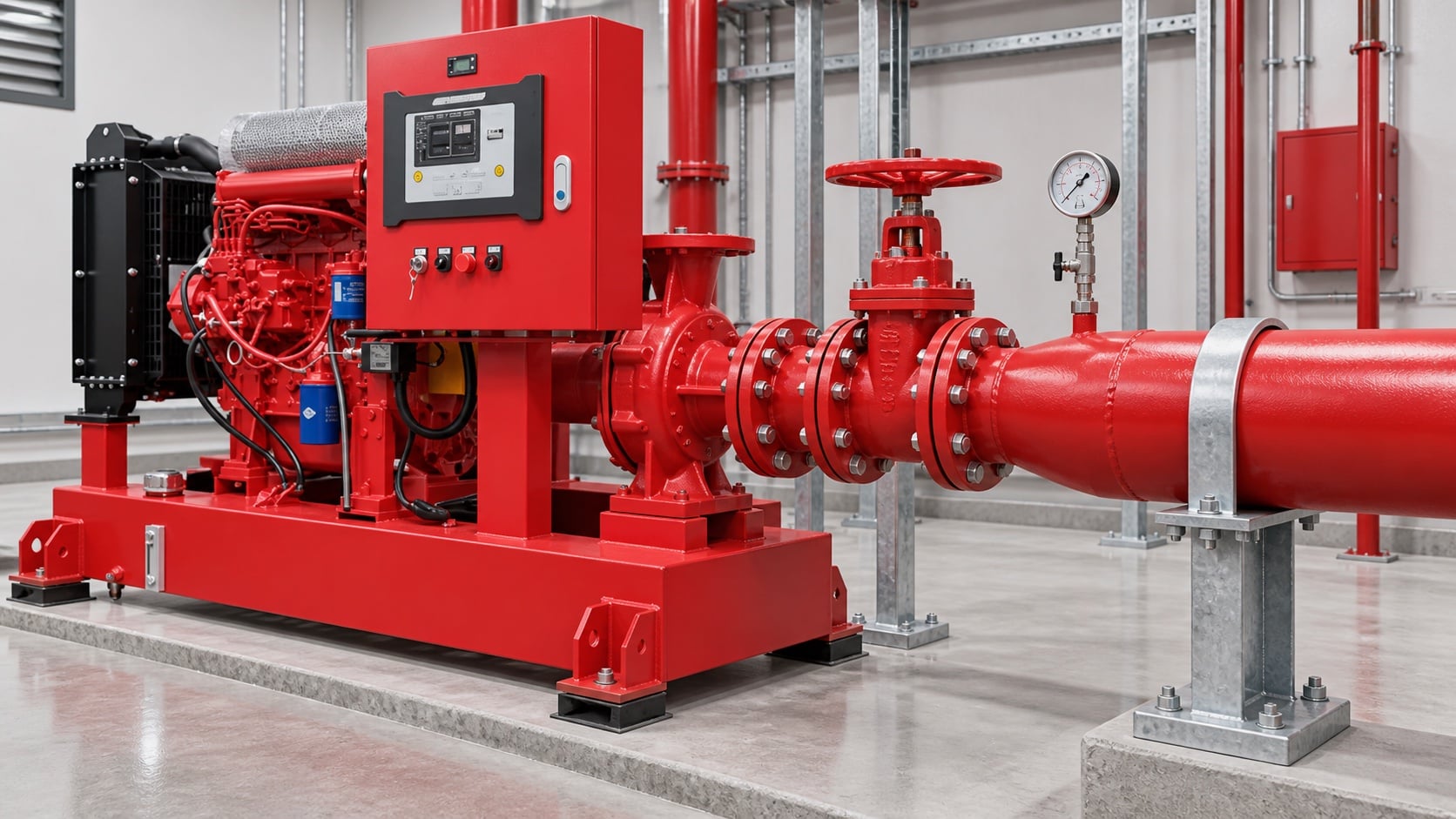
Model pipe length, fittings, valves, strainers where permitted, tank outlet, elevation, and entrance losses. Use the actual internal diameter and appropriate roughness. Review this condition at normal, test, and credible abnormal states before procurement. Identify the source of every input, the unit used, the operating condition it represents, and the person responsible for approval. If information is preliminary, mark the assumption and test how the decision changes at a conservative boundary. This prevents a neat calculation from hiding an uncertain water level, pressure, valve position, driver condition, or simultaneous demand.
For fire pump suction pipe sizing, verify this section against the selected pump curve, the actual site arrangement, manufacturer instructions, and the current requirements accepted by the authority having jurisdiction. Check the installed condition as well as the drawing because pipe routes, elevations, supports, controls, and access often change during construction. Record the result in a form that can be repeated during commissioning and later inspection. Do not change a safety-critical setting or isolate fire protection without the approved impairment and restoration process.
Protect available suction pressure
Combine source level or supply curve with suction loss and vapor-pressure considerations. A positive static level does not guarantee adequate pressure at high flow. The design team should turn this point into a traceable calculation or drawing note. Identify the source of every input, the unit used, the operating condition it represents, and the person responsible for approval. If information is preliminary, mark the assumption and test how the decision changes at a conservative boundary. This prevents a neat calculation from hiding an uncertain water level, pressure, valve position, driver condition, or simultaneous demand.
For fire pump suction pipe sizing, verify this section against the selected pump curve, the actual site arrangement, manufacturer instructions, and the current requirements accepted by the authority having jurisdiction. Check the installed condition as well as the drawing because pipe routes, elevations, supports, controls, and access often change during construction. Record the result in a form that can be repeated during commissioning and later inspection. Do not change a safety-critical setting or isolate fire protection without the approved impairment and restoration process.
Pratik karar tablosu
| Kontrol et | Acceptable evidence | Common mistake |
|---|---|---|
| Maximum flow | Approved system and test demand | Using rated flow only |
| Internal diameter | Pipe schedule and measured route | Using nominal size in calculations |
| Fittings | As-built count and geometry | Ignoring entrance and elbow losses |
| Source condition | Low tank level or current supply curve | Using static pressure only |
| Destekler | Independent support and alignment record | Pulling pipe into the flange |
| Air management | Continuous route without unintended high points | Creating an air pocket |
Arrange reducers and fittings carefully
Use the reducer orientation and straight-run arrangement required for the pump configuration. Avoid high points that trap air and elbows that create distorted flow at the inlet. Treat this as a system condition rather than an isolated component choice. Identify the source of every input, the unit used, the operating condition it represents, and the person responsible for approval. If information is preliminary, mark the assumption and test how the decision changes at a conservative boundary. This prevents a neat calculation from hiding an uncertain water level, pressure, valve position, driver condition, or simultaneous demand.
For fire pump suction pipe sizing, verify this section against the selected pump curve, the actual site arrangement, manufacturer instructions, and the current requirements accepted by the authority having jurisdiction. Check the installed condition as well as the drawing because pipe routes, elevations, supports, controls, and access often change during construction. Record the result in a form that can be repeated during commissioning and later inspection. Do not change a safety-critical setting or isolate fire protection without the approved impairment and restoration process.
Keep pipe loads off the pump
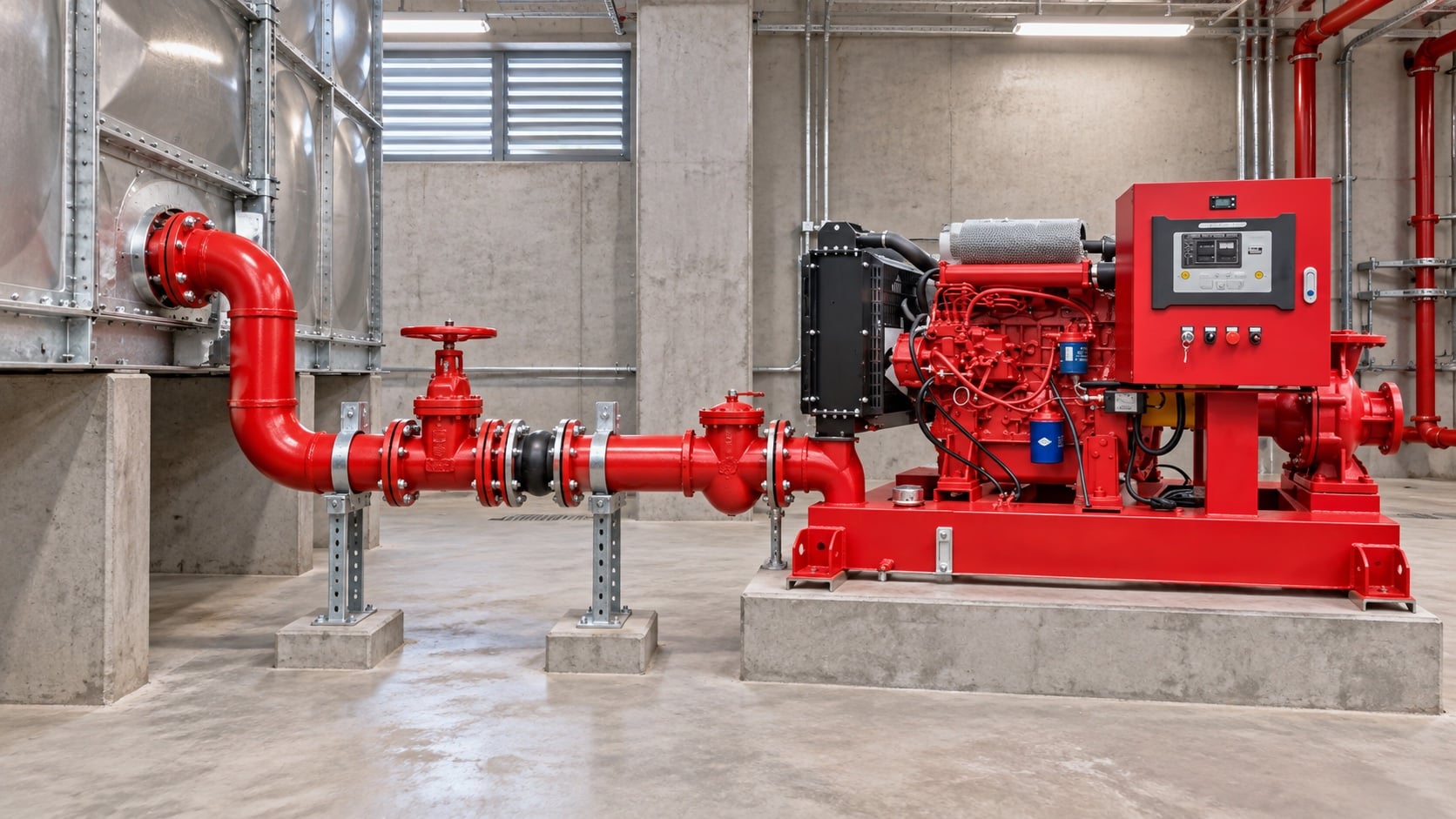
Provide independent supports and verified alignment. The pump nozzle must not carry the weight or thermal movement of the suction pipe. The most useful evidence is measured or approved project data, not a copied rule of thumb. Identify the source of every input, the unit used, the operating condition it represents, and the person responsible for approval. If information is preliminary, mark the assumption and test how the decision changes at a conservative boundary. This prevents a neat calculation from hiding an uncertain water level, pressure, valve position, driver condition, or simultaneous demand.
For fire pump suction pipe sizing, verify this section against the selected pump curve, the actual site arrangement, manufacturer instructions, and the current requirements accepted by the authority having jurisdiction. Check the installed condition as well as the drawing because pipe routes, elevations, supports, controls, and access often change during construction. Record the result in a form that can be repeated during commissioning and later inspection. Do not change a safety-critical setting or isolate fire protection without the approved impairment and restoration process.
Coordinate tanks and municipal supplies
For tanks, confirm usable low-water level and outlet behavior. For mains, use a current supply test and consider the lowest credible available pressure. Review this condition at normal, test, and credible abnormal states before procurement. Identify the source of every input, the unit used, the operating condition it represents, and the person responsible for approval. If information is preliminary, mark the assumption and test how the decision changes at a conservative boundary. This prevents a neat calculation from hiding an uncertain water level, pressure, valve position, driver condition, or simultaneous demand.
For fire pump suction pipe sizing, verify this section against the selected pump curve, the actual site arrangement, manufacturer instructions, and the current requirements accepted by the authority having jurisdiction. Check the installed condition as well as the drawing because pipe routes, elevations, supports, controls, and access often change during construction. Record the result in a form that can be repeated during commissioning and later inspection. Do not change a safety-critical setting or isolate fire protection without the approved impairment and restoration process.
Inspect and test the installed route
Compare as-built pipe with drawings, verify valve position and accessibility, flush debris, then record suction pressure across the required flow range. The design team should turn this point into a traceable calculation or drawing note. Identify the source of every input, the unit used, the operating condition it represents, and the person responsible for approval. If information is preliminary, mark the assumption and test how the decision changes at a conservative boundary. This prevents a neat calculation from hiding an uncertain water level, pressure, valve position, driver condition, or simultaneous demand.
For fire pump suction pipe sizing, verify this section against the selected pump curve, the actual site arrangement, manufacturer instructions, and the current requirements accepted by the authority having jurisdiction. Check the installed condition as well as the drawing because pipe routes, elevations, supports, controls, and access often change during construction. Record the result in a form that can be repeated during commissioning and later inspection. Do not change a safety-critical setting or isolate fire protection without the approved impairment and restoration process.
Bunun BORRAPUMP ekipmanıyla nasıl ilişkili olduğu
BORRAPUMP, su ve yangından korunma projeleri için mühendislik ürünü pompalama ekipmanları tedarik etmektedir. İlgili konuyu inceleyin. BORRAPUMP ürün konfigürasyonu Başlangıç noktası olarak gerekli debiyi, basma yüksekliğini, su kaynağını, sürücüyü, gücü, kumandaları, saha koşullarını, geçerli gereksinimleri, miktarı ve varış yerini iletin. Nihai seçim proje hidrolik temelini ve onaylı alt malzemeyi kullanmalıdır; bu kılavuz, hiçbir katalog düzenlemesinin her yargı bölgesine veya risk durumuna uyduğunu iddia etmez.
İlgili BORRAPUMP kılavuzları
Yetkin kaynaklar
Aşağıdaki kaynaklar, bu kılavuzda kullanılan standart sınırını, yangın güvenliği bağlamını ve pompa sistemi ilkelerini belirler. Proje için kabul edilen baskıyı ve yerel uyarlamayı her zaman uygulayın.
- NFPA 20 standart geliştirme sayfası
- ABD Enerji Bakanlığı pompalama sistemi kaynakları
- NIST yangın koruma araştırması
Eğitici video

Pratical Engineering'in eğitim geçmişi: Pompalar Basınç mı Yoksa Akış mı Oluşturur?. Video, temel mühendislik konseptini desteklemekte olup projeye özel yangından korunma gerekliliklerinin yerine geçmez.
Sık sorulan sorular
Emiş borusu pompa giriş boyutuyla aynı olabilir mi?
Otomatik olarak değil. Gerekli debiyi, hızı, yük kaybını, mevcut basıncı ve geçerli montaj kurallarını kontrol edin.
Giriş ağzına yakın bir dirsek neden endişe kaynağıdır?
Pompa girişinde düzensiz hız ve girdap oluşturabilir. Pompa ve proje yerleşim gereksinimlerine uyun.
Boyutlandırma yaparken test akışını dahil ediyor muyum?
Evet, onaylanmış test ve çalışma sırasında gereksiken en yüksek akışı değerlendirin.
Pozitif tank seviyesi kavitasyonu önlemek için yeterli mi?
Hayır. Mevcut basınç ayrıca kayıplara, sıcaklığa, atmosfer basıncına ve pompa gereksinimine de bağlıdır.
Son doğrulama kontrol listesi
Onaydan önce hidrolik temeli, su kaynağı koşulunu, seçilen pompa eğrisini, sürücü ve kontrolcü verilerini, bileşen basınç sınıflarını, vana düzenini, test yöntemini, erişimi, drenajı, alarmları ve eski haline getirme prosedürünü onaylayın. Projeler ile kurulan sistem arasındaki farkları giderin. Devreye alma sırasında kalibre edilmiş cihazlar kullanın ve gerekli her noktada emme basıncını, basma basıncını, debiyi, hızı, sürücü durumunu, alarmları ve anormal gözlemleri kaydedin. Sonraki denetimlerin benzeri benzeriyle karşılaştırabilmesi için kabul edilen sonuçları pompa odası kayıtlarıyla birlikte saklayın.