
Size a fire pump suction pipe from the required maximum test and system flow, acceptable velocity and friction loss, the available suction pressure, and the geometry required by the pump and applicable standard. The pipe must deliver water without excessive turbulence, air pockets, or avoidable loss. A diameter chosen only to match the pump nozzle can be too small, while a larger pipe with poor reducers, elbows, or unsupported loads can still cause unreliable suction performance. Keep the calculation and acceptance record with the final project documents so future tests use the same basis.
Seguridad y alcance: Las bombas contra incendios y sus motores son equipos de seguridad para la vida. Los trabajos hidráulicos, eléctricos, diésel, de combustible, de baterías, de presión, de equipos rotativos, de prueba y de deficiencias deben seguir el diseño aprobado vigente, las instrucciones del fabricante, las normas aplicables y la autoridad competente. Esta guía explica la ruta de decisiones de ingeniería; no autoriza cambios en campo, derivaciones ni la operación por personal no calificado.
- Define the maximum suction flow
- Use continuity to screen velocity
- Calculate suction-side friction
- Protect available suction pressure
- Arrange reducers and fittings carefully
- Keep pipe loads off the pump
- Coordinate tanks and municipal supplies
- Inspect and test the installed route
- Tabla de decisiones
- Preguntas frecuentes
Define the maximum suction flow
Use the highest flow that the approved pump test or system scenario requires, not only the nominal pump rating. Include simultaneous demand where the design basis requires it. Treat this as a system condition rather than an isolated component choice. Identify the source of every input, the unit used, the operating condition it represents, and the person responsible for approval. If information is preliminary, mark the assumption and test how the decision changes at a conservative boundary. This prevents a neat calculation from hiding an uncertain water level, pressure, valve position, driver condition, or simultaneous demand.
For fire pump suction pipe sizing, verify this section against the selected pump curve, the actual site arrangement, manufacturer instructions, and the current requirements accepted by the authority having jurisdiction. Check the installed condition as well as the drawing because pipe routes, elevations, supports, controls, and access often change during construction. Record the result in a form that can be repeated during commissioning and later inspection. Do not change a safety-critical setting or isolate fire protection without the approved impairment and restoration process.
Use continuity to screen velocity
Calculate velocity from Q divided by pipe area. Treat the result as a screening input, then confirm the current project requirements and the effect of fittings and entrance conditions. The most useful evidence is measured or approved project data, not a copied rule of thumb. Identify the source of every input, the unit used, the operating condition it represents, and the person responsible for approval. If information is preliminary, mark the assumption and test how the decision changes at a conservative boundary. This prevents a neat calculation from hiding an uncertain water level, pressure, valve position, driver condition, or simultaneous demand.
For fire pump suction pipe sizing, verify this section against the selected pump curve, the actual site arrangement, manufacturer instructions, and the current requirements accepted by the authority having jurisdiction. Check the installed condition as well as the drawing because pipe routes, elevations, supports, controls, and access often change during construction. Record the result in a form that can be repeated during commissioning and later inspection. Do not change a safety-critical setting or isolate fire protection without the approved impairment and restoration process.
Calculate suction-side friction
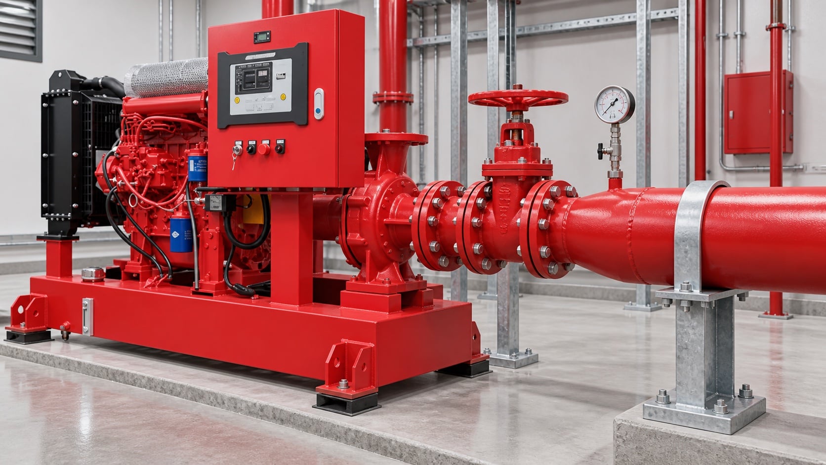
Model pipe length, fittings, valves, strainers where permitted, tank outlet, elevation, and entrance losses. Use the actual internal diameter and appropriate roughness. Review this condition at normal, test, and credible abnormal states before procurement. Identify the source of every input, the unit used, the operating condition it represents, and the person responsible for approval. If information is preliminary, mark the assumption and test how the decision changes at a conservative boundary. This prevents a neat calculation from hiding an uncertain water level, pressure, valve position, driver condition, or simultaneous demand.
For fire pump suction pipe sizing, verify this section against the selected pump curve, the actual site arrangement, manufacturer instructions, and the current requirements accepted by the authority having jurisdiction. Check the installed condition as well as the drawing because pipe routes, elevations, supports, controls, and access often change during construction. Record the result in a form that can be repeated during commissioning and later inspection. Do not change a safety-critical setting or isolate fire protection without the approved impairment and restoration process.
Protect available suction pressure
Combine source level or supply curve with suction loss and vapor-pressure considerations. A positive static level does not guarantee adequate pressure at high flow. The design team should turn this point into a traceable calculation or drawing note. Identify the source of every input, the unit used, the operating condition it represents, and the person responsible for approval. If information is preliminary, mark the assumption and test how the decision changes at a conservative boundary. This prevents a neat calculation from hiding an uncertain water level, pressure, valve position, driver condition, or simultaneous demand.
For fire pump suction pipe sizing, verify this section against the selected pump curve, the actual site arrangement, manufacturer instructions, and the current requirements accepted by the authority having jurisdiction. Check the installed condition as well as the drawing because pipe routes, elevations, supports, controls, and access often change during construction. Record the result in a form that can be repeated during commissioning and later inspection. Do not change a safety-critical setting or isolate fire protection without the approved impairment and restoration process.
Tabla de decisiones práctica
| Comprobar | Acceptable evidence | Common mistake |
|---|---|---|
| Maximum flow | Approved system and test demand | Using rated flow only |
| Internal diameter | Pipe schedule and measured route | Using nominal size in calculations |
| Fittings | As-built count and geometry | Ignoring entrance and elbow losses |
| Source condition | Low tank level or current supply curve | Using static pressure only |
| Compatible | Independent support and alignment record | Pulling pipe into the flange |
| Air management | Continuous route without unintended high points | Creating an air pocket |
Arrange reducers and fittings carefully
Use the reducer orientation and straight-run arrangement required for the pump configuration. Avoid high points that trap air and elbows that create distorted flow at the inlet. Treat this as a system condition rather than an isolated component choice. Identify the source of every input, the unit used, the operating condition it represents, and the person responsible for approval. If information is preliminary, mark the assumption and test how the decision changes at a conservative boundary. This prevents a neat calculation from hiding an uncertain water level, pressure, valve position, driver condition, or simultaneous demand.
For fire pump suction pipe sizing, verify this section against the selected pump curve, the actual site arrangement, manufacturer instructions, and the current requirements accepted by the authority having jurisdiction. Check the installed condition as well as the drawing because pipe routes, elevations, supports, controls, and access often change during construction. Record the result in a form that can be repeated during commissioning and later inspection. Do not change a safety-critical setting or isolate fire protection without the approved impairment and restoration process.
Keep pipe loads off the pump
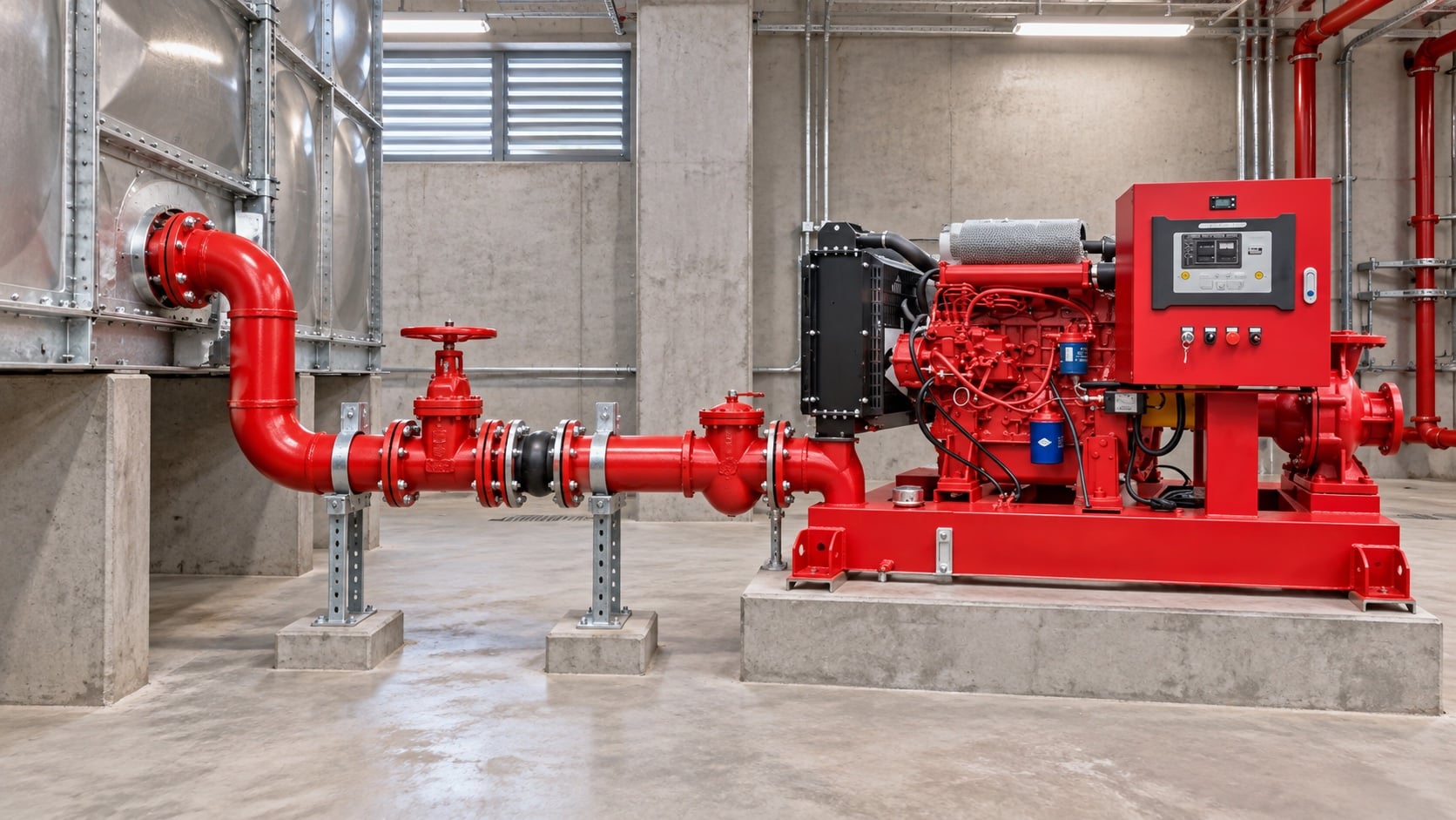
Provide independent supports and verified alignment. The pump nozzle must not carry the weight or thermal movement of the suction pipe. The most useful evidence is measured or approved project data, not a copied rule of thumb. Identify the source of every input, the unit used, the operating condition it represents, and the person responsible for approval. If information is preliminary, mark the assumption and test how the decision changes at a conservative boundary. This prevents a neat calculation from hiding an uncertain water level, pressure, valve position, driver condition, or simultaneous demand.
For fire pump suction pipe sizing, verify this section against the selected pump curve, the actual site arrangement, manufacturer instructions, and the current requirements accepted by the authority having jurisdiction. Check the installed condition as well as the drawing because pipe routes, elevations, supports, controls, and access often change during construction. Record the result in a form that can be repeated during commissioning and later inspection. Do not change a safety-critical setting or isolate fire protection without the approved impairment and restoration process.
Coordinate tanks and municipal supplies
For tanks, confirm usable low-water level and outlet behavior. For mains, use a current supply test and consider the lowest credible available pressure. Review this condition at normal, test, and credible abnormal states before procurement. Identify the source of every input, the unit used, the operating condition it represents, and the person responsible for approval. If information is preliminary, mark the assumption and test how the decision changes at a conservative boundary. This prevents a neat calculation from hiding an uncertain water level, pressure, valve position, driver condition, or simultaneous demand.
For fire pump suction pipe sizing, verify this section against the selected pump curve, the actual site arrangement, manufacturer instructions, and the current requirements accepted by the authority having jurisdiction. Check the installed condition as well as the drawing because pipe routes, elevations, supports, controls, and access often change during construction. Record the result in a form that can be repeated during commissioning and later inspection. Do not change a safety-critical setting or isolate fire protection without the approved impairment and restoration process.
Inspect and test the installed route
Compare as-built pipe with drawings, verify valve position and accessibility, flush debris, then record suction pressure across the required flow range. The design team should turn this point into a traceable calculation or drawing note. Identify the source of every input, the unit used, the operating condition it represents, and the person responsible for approval. If information is preliminary, mark the assumption and test how the decision changes at a conservative boundary. This prevents a neat calculation from hiding an uncertain water level, pressure, valve position, driver condition, or simultaneous demand.
For fire pump suction pipe sizing, verify this section against the selected pump curve, the actual site arrangement, manufacturer instructions, and the current requirements accepted by the authority having jurisdiction. Check the installed condition as well as the drawing because pipe routes, elevations, supports, controls, and access often change during construction. Record the result in a form that can be repeated during commissioning and later inspection. Do not change a safety-critical setting or isolate fire protection without the approved impairment and restoration process.
Cómo se relaciona esto con el equipo BORRAPUMP
BORRAPUMP suministra equipos de bombeo diseñados para proyectos de agua y protección contra incendios. Revise el correspondiente configuración del producto BORRAPUMP como punto de partida, luego presente el flujo requerido, la carga, la fuente de agua, el motor, la potencia, los controles, las condiciones del sitio, los requisitos aplicables, la cantidad y el destino. La selección final debe utilizar la base hidráulica del proyecto y la presentación aprobada; esta guía no afirma que una disposición de catálogo se adapte a todas las jurisdicciones o riesgos.
Guías relacionadas de BORRAPUMP
- bombas contra incendios diésel frente a eléctricas
- selección de equipo de bombeo contra incendio
- Guía de pruebas de aceptación NFPA 20
Referencias autorizadas
Las siguientes fuentes establecen el límite normativo, el contexto de seguridad contra incendios y los principios del sistema de bombas utilizados en esta guía. Aplique siempre la edición y la adopción local aceptadas para el proyecto.
- Página de desarrollo de la norma NFPA 20
- Recursos sobre sistemas de bombas del Departamento de Energía de EE. UU.
- Investigación sobre protección contra incendios del NIST
Video educativo

Antecedentes educativos por Practical Engineering: ¿Las bombas crean presión o caudal?. El video respalda el concepto de ingeniería subyacente y no reemplaza los requisitos de protección contra incendios específicos del proyecto.
Preguntas frecuentes
¿Puede la tubería de aspiración ser igual al tamaño de la entrada de la bomba?
No automáticamente. Verifique el caudal requerido, la velocidad, la pérdida, la presión disponible y las normas de instalación aplicables.
¿Por qué un codo cerca de la entrada es motivo de preocupación?
Puede crear una velocidad desigual y remolinos en la entrada de la bomba. Siga los requisitos de disposición de la bomba y del proyecto.
¿Incluyo el flujo de pruebas al dimensionar?
Sí, evalúe el flujo más alto requerido durante las pruebas y operación aprobadas.
¿Es suficiente un nivel de tanque positivo para prevenir la cavitación?
No. Available pressure also depends on losses, temperature, atmospheric pressure, and the pump requirement.
Lista de verificación de verificación final
Antes de la aprobación, confirme la base hidráulica, la condición de la fuente de agua, la curva de la bomba seleccionada, los datos del motor y del controlador, las presiones nominales de los componentes, la disposición de las válvulas, el método de prueba, el acceso, el drenaje, las alarmas y el procedimiento de restauración. Resuelva las diferencias entre los planos y el sistema instalado. Durante la puesta en marcha, utilice instrumentos calibrados y registre la presión de succión, la presión de descarga, el caudal, la velocidad, el estado del motor, las alarmas y las observaciones anormales en cada punto requerido. Guarde los resultados aceptados junto con los registros de la sala de bombas para que las inspecciones posteriores comparen elementos equivalentes.