
Size a fire pump suction pipe from the required maximum test and system flow, acceptable velocity and friction loss, the available suction pressure, and the geometry required by the pump and applicable standard. The pipe must deliver water without excessive turbulence, air pockets, or avoidable loss. A diameter chosen only to match the pump nozzle can be too small, while a larger pipe with poor reducers, elbows, or unsupported loads can still cause unreliable suction performance. Keep the calculation and acceptance record with the final project documents so future tests use the same basis.
An toàn và phạm vi: Máy bơm phòng cháy chữa cháy và các thiết bị truyền động của chúng là thiết bị an toàn tính mạng. Công việc liên quan đến thủy lực, điện, dầu diesel, nhiên liệu, ắc quy, áp suất, thiết bị quay, thử nghiệm và khắc phục sự cố phải tuân theo thiết kế được phê duyệt hiện hành, hướng dẫn của nhà sản xuất, các tiêu chuẩn hiện hành và cơ quan có thẩm quyền. Hướng dẫn này giải thích lộ trình quyết định kỹ thuật; tài liệu này không cho phép thực hiện các thay đổi tại hiện trường, bỏ qua quy trình hoặc vận hành bởi nhân viên không đủ năng lực.
- Define the maximum suction flow
- Use continuity to screen velocity
- Calculate suction-side friction
- Protect available suction pressure
- Arrange reducers and fittings carefully
- Keep pipe loads off the pump
- Coordinate tanks and municipal supplies
- Inspect and test the installed route
- Bảng quyết định
- Các câu hỏi thường gặp
Define the maximum suction flow
Use the highest flow that the approved pump test or system scenario requires, not only the nominal pump rating. Include simultaneous demand where the design basis requires it. Treat this as a system condition rather than an isolated component choice. Identify the source of every input, the unit used, the operating condition it represents, and the person responsible for approval. If information is preliminary, mark the assumption and test how the decision changes at a conservative boundary. This prevents a neat calculation from hiding an uncertain water level, pressure, valve position, driver condition, or simultaneous demand.
For fire pump suction pipe sizing, verify this section against the selected pump curve, the actual site arrangement, manufacturer instructions, and the current requirements accepted by the authority having jurisdiction. Check the installed condition as well as the drawing because pipe routes, elevations, supports, controls, and access often change during construction. Record the result in a form that can be repeated during commissioning and later inspection. Do not change a safety-critical setting or isolate fire protection without the approved impairment and restoration process.
Use continuity to screen velocity
Calculate velocity from Q divided by pipe area. Treat the result as a screening input, then confirm the current project requirements and the effect of fittings and entrance conditions. The most useful evidence is measured or approved project data, not a copied rule of thumb. Identify the source of every input, the unit used, the operating condition it represents, and the person responsible for approval. If information is preliminary, mark the assumption and test how the decision changes at a conservative boundary. This prevents a neat calculation from hiding an uncertain water level, pressure, valve position, driver condition, or simultaneous demand.
For fire pump suction pipe sizing, verify this section against the selected pump curve, the actual site arrangement, manufacturer instructions, and the current requirements accepted by the authority having jurisdiction. Check the installed condition as well as the drawing because pipe routes, elevations, supports, controls, and access often change during construction. Record the result in a form that can be repeated during commissioning and later inspection. Do not change a safety-critical setting or isolate fire protection without the approved impairment and restoration process.
Calculate suction-side friction
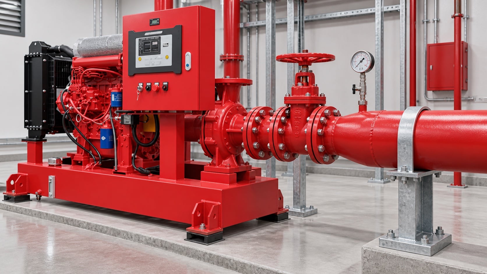
Model pipe length, fittings, valves, strainers where permitted, tank outlet, elevation, and entrance losses. Use the actual internal diameter and appropriate roughness. Review this condition at normal, test, and credible abnormal states before procurement. Identify the source of every input, the unit used, the operating condition it represents, and the person responsible for approval. If information is preliminary, mark the assumption and test how the decision changes at a conservative boundary. This prevents a neat calculation from hiding an uncertain water level, pressure, valve position, driver condition, or simultaneous demand.
For fire pump suction pipe sizing, verify this section against the selected pump curve, the actual site arrangement, manufacturer instructions, and the current requirements accepted by the authority having jurisdiction. Check the installed condition as well as the drawing because pipe routes, elevations, supports, controls, and access often change during construction. Record the result in a form that can be repeated during commissioning and later inspection. Do not change a safety-critical setting or isolate fire protection without the approved impairment and restoration process.
Protect available suction pressure
Combine source level or supply curve with suction loss and vapor-pressure considerations. A positive static level does not guarantee adequate pressure at high flow. The design team should turn this point into a traceable calculation or drawing note. Identify the source of every input, the unit used, the operating condition it represents, and the person responsible for approval. If information is preliminary, mark the assumption and test how the decision changes at a conservative boundary. This prevents a neat calculation from hiding an uncertain water level, pressure, valve position, driver condition, or simultaneous demand.
For fire pump suction pipe sizing, verify this section against the selected pump curve, the actual site arrangement, manufacturer instructions, and the current requirements accepted by the authority having jurisdiction. Check the installed condition as well as the drawing because pipe routes, elevations, supports, controls, and access often change during construction. Record the result in a form that can be repeated during commissioning and later inspection. Do not change a safety-critical setting or isolate fire protection without the approved impairment and restoration process.
Bảng quyết định thực tế
| Kiểm tra | Acceptable evidence | Common mistake |
|---|---|---|
| Maximum flow | Approved system and test demand | Using rated flow only |
| Internal diameter | Pipe schedule and measured route | Using nominal size in calculations |
| Fittings | As-built count and geometry | Ignoring entrance and elbow losses |
| Source condition | Low tank level or current supply curve | Using static pressure only |
| Hỗ trợ | Independent support and alignment record | Pulling pipe into the flange |
| Air management | Continuous route without unintended high points | Creating an air pocket |
Arrange reducers and fittings carefully
Use the reducer orientation and straight-run arrangement required for the pump configuration. Avoid high points that trap air and elbows that create distorted flow at the inlet. Treat this as a system condition rather than an isolated component choice. Identify the source of every input, the unit used, the operating condition it represents, and the person responsible for approval. If information is preliminary, mark the assumption and test how the decision changes at a conservative boundary. This prevents a neat calculation from hiding an uncertain water level, pressure, valve position, driver condition, or simultaneous demand.
For fire pump suction pipe sizing, verify this section against the selected pump curve, the actual site arrangement, manufacturer instructions, and the current requirements accepted by the authority having jurisdiction. Check the installed condition as well as the drawing because pipe routes, elevations, supports, controls, and access often change during construction. Record the result in a form that can be repeated during commissioning and later inspection. Do not change a safety-critical setting or isolate fire protection without the approved impairment and restoration process.
Keep pipe loads off the pump
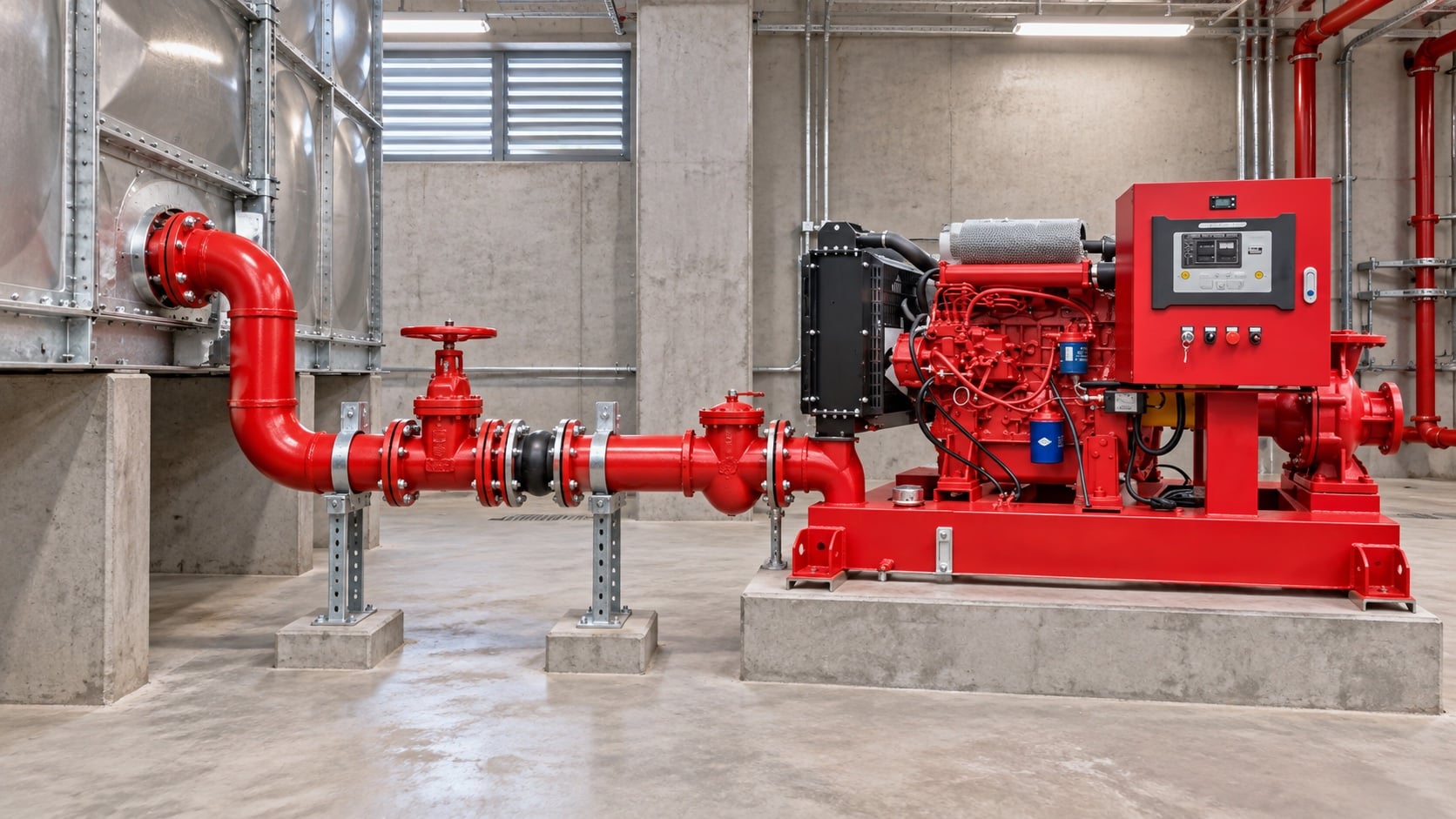
Provide independent supports and verified alignment. The pump nozzle must not carry the weight or thermal movement of the suction pipe. The most useful evidence is measured or approved project data, not a copied rule of thumb. Identify the source of every input, the unit used, the operating condition it represents, and the person responsible for approval. If information is preliminary, mark the assumption and test how the decision changes at a conservative boundary. This prevents a neat calculation from hiding an uncertain water level, pressure, valve position, driver condition, or simultaneous demand.
For fire pump suction pipe sizing, verify this section against the selected pump curve, the actual site arrangement, manufacturer instructions, and the current requirements accepted by the authority having jurisdiction. Check the installed condition as well as the drawing because pipe routes, elevations, supports, controls, and access often change during construction. Record the result in a form that can be repeated during commissioning and later inspection. Do not change a safety-critical setting or isolate fire protection without the approved impairment and restoration process.
Coordinate tanks and municipal supplies
For tanks, confirm usable low-water level and outlet behavior. For mains, use a current supply test and consider the lowest credible available pressure. Review this condition at normal, test, and credible abnormal states before procurement. Identify the source of every input, the unit used, the operating condition it represents, and the person responsible for approval. If information is preliminary, mark the assumption and test how the decision changes at a conservative boundary. This prevents a neat calculation from hiding an uncertain water level, pressure, valve position, driver condition, or simultaneous demand.
For fire pump suction pipe sizing, verify this section against the selected pump curve, the actual site arrangement, manufacturer instructions, and the current requirements accepted by the authority having jurisdiction. Check the installed condition as well as the drawing because pipe routes, elevations, supports, controls, and access often change during construction. Record the result in a form that can be repeated during commissioning and later inspection. Do not change a safety-critical setting or isolate fire protection without the approved impairment and restoration process.
Inspect and test the installed route
Compare as-built pipe with drawings, verify valve position and accessibility, flush debris, then record suction pressure across the required flow range. The design team should turn this point into a traceable calculation or drawing note. Identify the source of every input, the unit used, the operating condition it represents, and the person responsible for approval. If information is preliminary, mark the assumption and test how the decision changes at a conservative boundary. This prevents a neat calculation from hiding an uncertain water level, pressure, valve position, driver condition, or simultaneous demand.
For fire pump suction pipe sizing, verify this section against the selected pump curve, the actual site arrangement, manufacturer instructions, and the current requirements accepted by the authority having jurisdiction. Check the installed condition as well as the drawing because pipe routes, elevations, supports, controls, and access often change during construction. Record the result in a form that can be repeated during commissioning and later inspection. Do not change a safety-critical setting or isolate fire protection without the approved impairment and restoration process.
Điều này liên quan như thế nào đến thiết bị BORRAPUMP
BORRAPUMP cung cấp thiết bị bơm kỹ thuật cho các dự án cấp nước và phòng cháy chữa cháy. Xem lại phần liên quan Cấu hình sản phẩm BORRAPUMP làm điểm khởi đầu, sau đó gửi lưu lượng, cột áp, nguồn nước, động cơ, công suất, hệ thống điều khiển, điều kiện hiện trường, các yêu cầu hiện hành, số lượng và điểm đến được yêu cầu. Lựa chọn cuối cùng phải sử dụng cơ sở thủy lực của dự án và bản trình duyệt được phê duyệt; hướng dẫn này không khẳng định rằng một bố trí trong catalogue phù hợp với mọi khu vực tàijurisdiction hoặc rủi ro.
Các hướng dẫn BORRAPUMP liên quan
- máy bơm chữa cháy diesel và máy bơm chữa cháy điện
- lựa chọn cụm bơm phòng cháy chữa cháy
- Hướng dẫn kiểm tra nghiệm thu NFPA 20
Tài liệu tham khảo có thẩm quyền
Các nguồn sau đây thiết lập ranh giới tiêu chuẩn, bối cảnh an toàn phòng cháy chữa cháy và các nguyên tắc hệ thống bơm được sử dụng trong hướng dẫn này. Luôn áp dụng phiên bản và quy chuẩn địa phương được chấp thuận cho dự án.
- Trang phát triển tiêu chuẩn NFPA 20
- Tài nguyên hệ thống máy bơm của Bộ Năng lượng Hoa Kỳ
- Nghiên cứu phòng cháy chữa cháy của NIST
Video giáo dục

Nền tảng giáo dục bởi Practical Engineering: Máy bơm tạo ra áp suất hay lưu lượng?. Video hỗ trợ cho khái niệm kỹ thuật cơ bản và không thay thế các yêu cầu phòng cháy chữa cháy cụ thể của dự án.
Các câu hỏi thường gặp
Can the suction pipe equal the pump inlet size?
Not automatically. Check required flow, velocity, loss, available pressure, and the applicable installation rules.
Why is an elbow near the inlet a concern?
It can create uneven velocity and swirl at the pump inlet. Follow the pump and project arrangement requirements.
Do I include test flow when sizing?
Yes, evaluate the highest flow required during approved testing and operation.
Is positive tank level enough to prevent cavitation?
No. Available pressure also depends on losses, temperature, atmospheric pressure, and the pump requirement.
Danh sách kiểm tra xác minh cuối cùng
Trước khi phê duyệt, hãy xác nhận cơ sở thủy lực, điều kiện nguồn nước, đường cong bơm đã chọn, dữ liệu bộ truyền động và bộ điều khiển, định mức áp suất của các bộ phận, bố trí van, phương pháp thử nghiệm, lối đi, hệ thống thoát nước, cảnh báo và quy trình khôi phục. Giải quyết các khác biệt giữa bản vẽ và hệ thống thực tế đã lắp đặt. Trong quá trình chạy thử, hãy sử dụng các thiết bị đã hiệu chuẩn và ghi lại áp suất hút, áp suất xả, lưu lượng, tốc độ, tình trạng bộ truyền động, cảnh báo và các quan sát bất thường tại mọi điểm yêu cầu. Lưu giữ các kết quả đã được chấp nhận cùng với hồ sơ phòng bơm để các lần kiểm tra sau có thể so sánh các yếu tố tương đương.