
Size a fire pump suction pipe from the required maximum test and system flow, acceptable velocity and friction loss, the available suction pressure, and the geometry required by the pump and applicable standard. The pipe must deliver water without excessive turbulence, air pockets, or avoidable loss. A diameter chosen only to match the pump nozzle can be too small, while a larger pipe with poor reducers, elbows, or unsupported loads can still cause unreliable suction performance. Keep the calculation and acceptance record with the final project documents so future tests use the same basis.
Sicherheit und Geltungsbereich: Feuerlöschpumpen und deren Antriebe sind lebensrettende Einrichtungen. Arbeiten an Hydraulik, Elektrik, Diesel, Kraftstoff, Batterie, Druck, rotierenden Geräten, Prüfungen und Betriebsstörungen müssen dem aktuellen genehmigten Entwurf, den Herstelleranweisungen, den geltenden Normen und der zuständigen Behörde entsprechen. Dieser Leitfaden erläutert den ingenieurtechnischen Entscheidungsweg; er berechtigt nicht zu Änderungen vor Ort, Umgehungen oder zum Betrieb durch unqualifiziertes Personal.
- Define the maximum suction flow
- Use continuity to screen velocity
- Calculate suction-side friction
- Protect available suction pressure
- Arrange reducers and fittings carefully
- Keep pipe loads off the pump
- Coordinate tanks and municipal supplies
- Inspect and test the installed route
- Entscheidungstabelle
- Häufig gestellte Fragen
Define the maximum suction flow
Use the highest flow that the approved pump test or system scenario requires, not only the nominal pump rating. Include simultaneous demand where the design basis requires it. Treat this as a system condition rather than an isolated component choice. Identify the source of every input, the unit used, the operating condition it represents, and the person responsible for approval. If information is preliminary, mark the assumption and test how the decision changes at a conservative boundary. This prevents a neat calculation from hiding an uncertain water level, pressure, valve position, driver condition, or simultaneous demand.
For fire pump suction pipe sizing, verify this section against the selected pump curve, the actual site arrangement, manufacturer instructions, and the current requirements accepted by the authority having jurisdiction. Check the installed condition as well as the drawing because pipe routes, elevations, supports, controls, and access often change during construction. Record the result in a form that can be repeated during commissioning and later inspection. Do not change a safety-critical setting or isolate fire protection without the approved impairment and restoration process.
Use continuity to screen velocity
Calculate velocity from Q divided by pipe area. Treat the result as a screening input, then confirm the current project requirements and the effect of fittings and entrance conditions. The most useful evidence is measured or approved project data, not a copied rule of thumb. Identify the source of every input, the unit used, the operating condition it represents, and the person responsible for approval. If information is preliminary, mark the assumption and test how the decision changes at a conservative boundary. This prevents a neat calculation from hiding an uncertain water level, pressure, valve position, driver condition, or simultaneous demand.
For fire pump suction pipe sizing, verify this section against the selected pump curve, the actual site arrangement, manufacturer instructions, and the current requirements accepted by the authority having jurisdiction. Check the installed condition as well as the drawing because pipe routes, elevations, supports, controls, and access often change during construction. Record the result in a form that can be repeated during commissioning and later inspection. Do not change a safety-critical setting or isolate fire protection without the approved impairment and restoration process.
Calculate suction-side friction
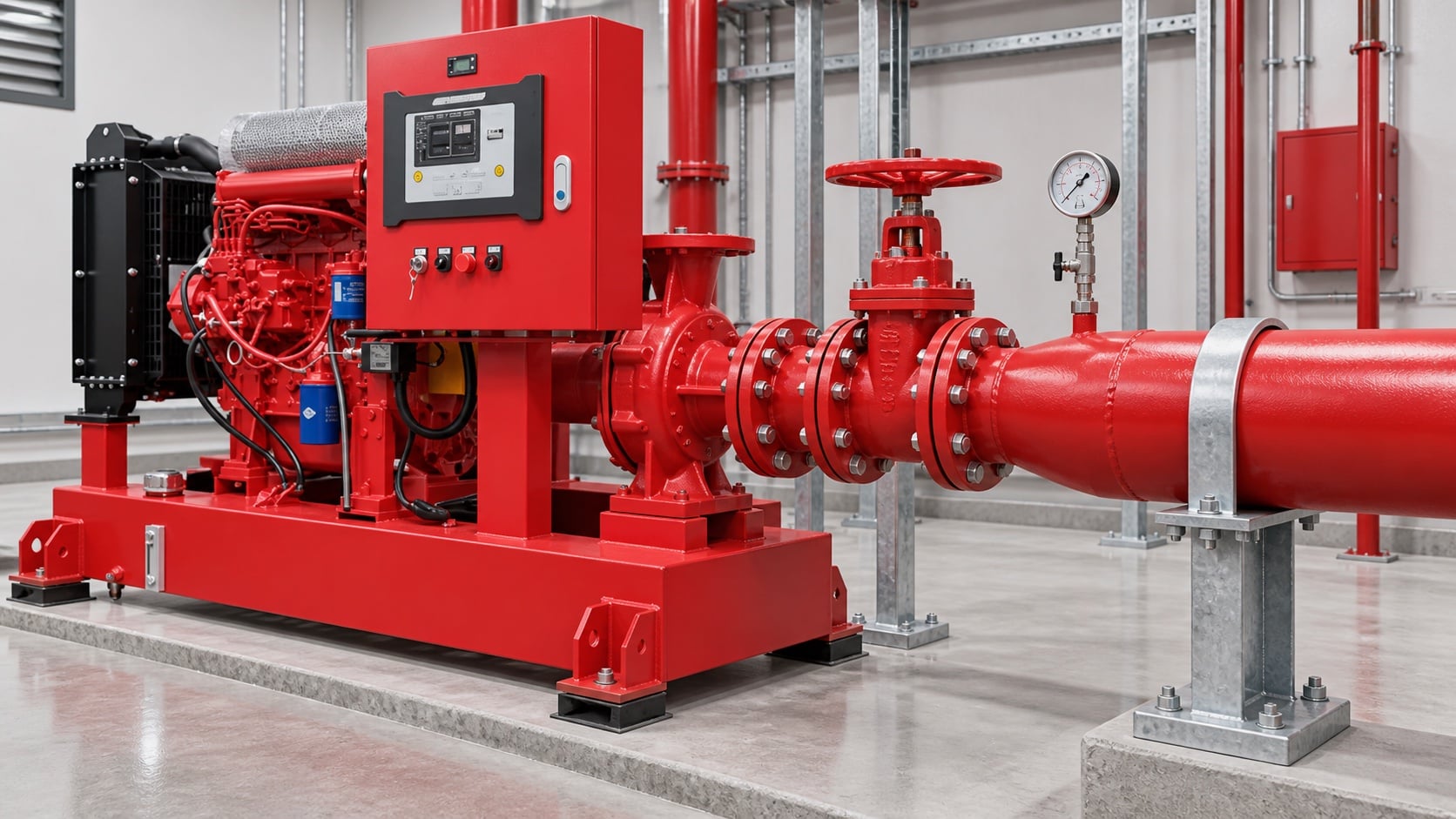
Model pipe length, fittings, valves, strainers where permitted, tank outlet, elevation, and entrance losses. Use the actual internal diameter and appropriate roughness. Review this condition at normal, test, and credible abnormal states before procurement. Identify the source of every input, the unit used, the operating condition it represents, and the person responsible for approval. If information is preliminary, mark the assumption and test how the decision changes at a conservative boundary. This prevents a neat calculation from hiding an uncertain water level, pressure, valve position, driver condition, or simultaneous demand.
For fire pump suction pipe sizing, verify this section against the selected pump curve, the actual site arrangement, manufacturer instructions, and the current requirements accepted by the authority having jurisdiction. Check the installed condition as well as the drawing because pipe routes, elevations, supports, controls, and access often change during construction. Record the result in a form that can be repeated during commissioning and later inspection. Do not change a safety-critical setting or isolate fire protection without the approved impairment and restoration process.
Protect available suction pressure
Combine source level or supply curve with suction loss and vapor-pressure considerations. A positive static level does not guarantee adequate pressure at high flow. The design team should turn this point into a traceable calculation or drawing note. Identify the source of every input, the unit used, the operating condition it represents, and the person responsible for approval. If information is preliminary, mark the assumption and test how the decision changes at a conservative boundary. This prevents a neat calculation from hiding an uncertain water level, pressure, valve position, driver condition, or simultaneous demand.
For fire pump suction pipe sizing, verify this section against the selected pump curve, the actual site arrangement, manufacturer instructions, and the current requirements accepted by the authority having jurisdiction. Check the installed condition as well as the drawing because pipe routes, elevations, supports, controls, and access often change during construction. Record the result in a form that can be repeated during commissioning and later inspection. Do not change a safety-critical setting or isolate fire protection without the approved impairment and restoration process.
Praktische Entscheidungstabelle
| Prüfen | Acceptable evidence | Common mistake |
|---|---|---|
| Maximum flow | Approved system and test demand | Using rated flow only |
| Internal diameter | Pipe schedule and measured route | Using nominal size in calculations |
| Fittings | As-built count and geometry | Ignoring entrance and elbow losses |
| Source condition | Low tank level or current supply curve | Using static pressure only |
| Unterstützt | Independent support and alignment record | Pulling pipe into the flange |
| Air management | Continuous route without unintended high points | Creating an air pocket |
Arrange reducers and fittings carefully
Use the reducer orientation and straight-run arrangement required for the pump configuration. Avoid high points that trap air and elbows that create distorted flow at the inlet. Treat this as a system condition rather than an isolated component choice. Identify the source of every input, the unit used, the operating condition it represents, and the person responsible for approval. If information is preliminary, mark the assumption and test how the decision changes at a conservative boundary. This prevents a neat calculation from hiding an uncertain water level, pressure, valve position, driver condition, or simultaneous demand.
For fire pump suction pipe sizing, verify this section against the selected pump curve, the actual site arrangement, manufacturer instructions, and the current requirements accepted by the authority having jurisdiction. Check the installed condition as well as the drawing because pipe routes, elevations, supports, controls, and access often change during construction. Record the result in a form that can be repeated during commissioning and later inspection. Do not change a safety-critical setting or isolate fire protection without the approved impairment and restoration process.
Keep pipe loads off the pump
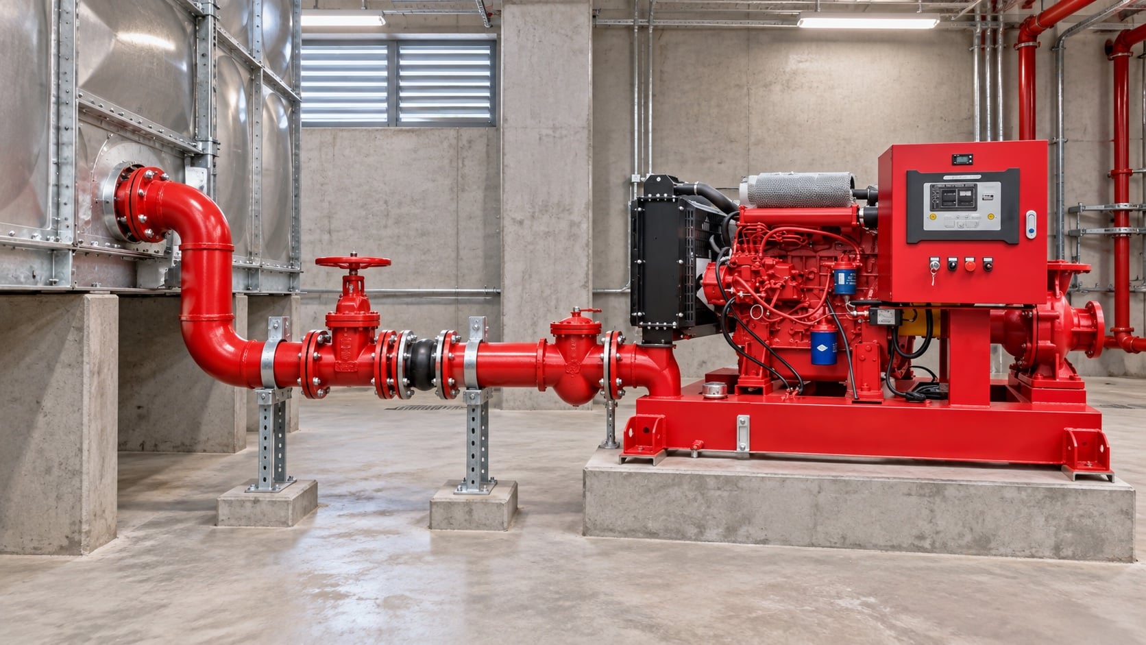
Provide independent supports and verified alignment. The pump nozzle must not carry the weight or thermal movement of the suction pipe. The most useful evidence is measured or approved project data, not a copied rule of thumb. Identify the source of every input, the unit used, the operating condition it represents, and the person responsible for approval. If information is preliminary, mark the assumption and test how the decision changes at a conservative boundary. This prevents a neat calculation from hiding an uncertain water level, pressure, valve position, driver condition, or simultaneous demand.
For fire pump suction pipe sizing, verify this section against the selected pump curve, the actual site arrangement, manufacturer instructions, and the current requirements accepted by the authority having jurisdiction. Check the installed condition as well as the drawing because pipe routes, elevations, supports, controls, and access often change during construction. Record the result in a form that can be repeated during commissioning and later inspection. Do not change a safety-critical setting or isolate fire protection without the approved impairment and restoration process.
Coordinate tanks and municipal supplies
For tanks, confirm usable low-water level and outlet behavior. For mains, use a current supply test and consider the lowest credible available pressure. Review this condition at normal, test, and credible abnormal states before procurement. Identify the source of every input, the unit used, the operating condition it represents, and the person responsible for approval. If information is preliminary, mark the assumption and test how the decision changes at a conservative boundary. This prevents a neat calculation from hiding an uncertain water level, pressure, valve position, driver condition, or simultaneous demand.
For fire pump suction pipe sizing, verify this section against the selected pump curve, the actual site arrangement, manufacturer instructions, and the current requirements accepted by the authority having jurisdiction. Check the installed condition as well as the drawing because pipe routes, elevations, supports, controls, and access often change during construction. Record the result in a form that can be repeated during commissioning and later inspection. Do not change a safety-critical setting or isolate fire protection without the approved impairment and restoration process.
Inspect and test the installed route
Compare as-built pipe with drawings, verify valve position and accessibility, flush debris, then record suction pressure across the required flow range. The design team should turn this point into a traceable calculation or drawing note. Identify the source of every input, the unit used, the operating condition it represents, and the person responsible for approval. If information is preliminary, mark the assumption and test how the decision changes at a conservative boundary. This prevents a neat calculation from hiding an uncertain water level, pressure, valve position, driver condition, or simultaneous demand.
For fire pump suction pipe sizing, verify this section against the selected pump curve, the actual site arrangement, manufacturer instructions, and the current requirements accepted by the authority having jurisdiction. Check the installed condition as well as the drawing because pipe routes, elevations, supports, controls, and access often change during construction. Record the result in a form that can be repeated during commissioning and later inspection. Do not change a safety-critical setting or isolate fire protection without the approved impairment and restoration process.
Wie dies sich auf BORRAPUMP-Ausrüstung bezieht
BORRAPUMP liefert technische Pumpenausrüstung für Wasser- und Brandschutzprojekte. Überprüfen Sie die relevanten BORRAPUMP-Produktkonfiguration als Ausgangspunkt, reichen Sie dann den erforderlichen Volumenstrom, die Förderhöhe, die Wasserquelle, den Antrieb, die Leistung, die Steuerungen, die Baustellenbedingungen, die geltenden Anforderungen, die Stückzahl und den Bestimmungsort ein. Die endgültige Auswahl muss auf der hydraulischen Projektbasis und der genehmigten Einreichung basieren; dieser Leitfaden erhebt keinen Anspruch darauf, dass eine Kataloganordnung für jede Jurisdiktion oder jedes Risiko passt.
Ähnliche BORRAPUMP-Anleitungen
- Diesel- versus Elektrojahrlöschanlagen
- Auswahl der Feuerlöschpumpen-Einheit
- NFPA 20 Abnahmeprüfungs-Leitfaden
Maßgebliche Referenzen
Die folgenden Quellen legen den Normenbereich, den Brandschutzkontext und die Pumpensystemprinzipien fest, die in diesem Leitfaden verwendet werden. Wenden Sie stets die für das Projekt akzeptierte Ausgabe und lokale Einführung an.
- NFPA 20 Normenentwicklungsseite
- Ressourcen für Pumpensysteme des US-Energieministeriums
- NIST-Forschung zum Brandschutz
Lernvideo

Bildungshintergrund von Practical Engineering: Erzeugen Pumpen Druck oder Fluss?. Das Video unterstützt das zugrundeliegende ingenieurtechnische Konzept und ersetzt nicht die projektspezifischen Brandschutzanforderungen.
Häufig gestellte Fragen
Kann die Saugleitung die Größe des Pumpeneinlasses haben?
Nicht automatisch. Überprüfen Sie den erforderlichen Durchfluss, die Geschwindigkeit, den Verlust, den verfügbaren Druck und die geltenden Installationsregeln.
Warum bereitet ein Rohrbogen in der Nähe des Einlasses Sorge?
Dies kann zu ungleichmäßigen Strömungsgeschwindigkeiten und Verwirbelungen am Pumpeneinlass führen. Beachten Sie die Anforderungen zur Anordnung von Pumpe und Anlage.
Schließe ich den Testablauf bei der Dimensionierung ein?
Ja, bewerten Sie den höchsten Durchfluss, der während genehmigter Tests und des Betriebs erforderlich ist.
Reicht ein positiver Tankstand aus, um Kavitation zu verhindern?
No. Available pressure also depends on losses, temperature, atmospheric pressure, and the pump requirement.
Abschließende Prüfliste
Vor der Freigabe sind die hydraulischen Grundlagen, die Wasserquellenbedingungen, die ausgewählte Pumpenkennlinie, die Daten von Antrieb und Steuerung, die Nenndrücke der Komponenten, die Ventilanordnung, das Prüfverfahren, die Zugänglichkeit, die Entwässerung, die Alarme und das Wiederherstellungsverfahren zu bestätigen. Differenzen zwischen den Zeichnungen und dem installierten System sind zu berechnen. Während der Inbetriebnahme sind kalibrierte Instrumente zu verwenden und Saugdruck, Förderdruck, Durchfluss, Drehzahl, Antriebszustand, Alarme und abweichende Beobachtungen an jedem geforderten Punkt aufzuzeichnen. Die akzeptierten Ergebnisse sind bei den Pumpenraumprotokollen aufzubewahren, damit spätere Inspektionen vergleichbare Werte liefern.