
A clogged pump suction pipe usually shows up as reduced flow, lower suction pressure, unstable discharge, noise, cavitation-like symptoms, longer fill time, or a change in motor load. Confirm the symptom with gauges and operating data before opening equipment. Then isolate and lock out the pump, remove pressure, verify the liquid hazard, and inspect the easiest restrictions first: source level, suction valve, strainer, foot valve, hose collapse, air leak, and intake blockage. Do not keep running a starved centrifugal pump; it can damage seals, impellers, bearings, and the liquid itself.
Dieser Leitfaden ist ein früher Ingenieur- und Beschaffungsrahmen und kein Ersatz für genehmigte Projektplanungen, geltende Vorschriften, Herstelleranweisungen oder qualifizierte Bauüberwachung. Elektroarbeiten, Arbeiten an unter Spannung stehenden Anlagen, Hebevorgänge, der Einstieg in enge Räume, Brandschutzarbeiten, Aushubarbeiten, Arbeiten mit gefährlichen Flüssigkeiten, Abwasser und Drucksystemen erfordern aufgaben spezifische Verfahren und kompetentes Personal. Bewahren Sie den automatischen Schutz und die Systemverfügbarkeit bei der Fehlersuche. Wenn die tatsächliche Flüssigkeit, die Beanspruchung, die Baustellenbedingung oder die geltende Anforderung von den Annahmen abweicht, stoppen Sie die Arbeiten und holen Sie eine überarbeitete technische Überprüfung ein.
- Recognize restriction without guessing
- Inspect source, valves, strainers, and flexible hose
- Find air leaks and loss of prime
- Isolate and remove an internal blockage safely
- Prevent repeat blockages through system design
- Recommission and verify the root cause is removed
- Entscheidungstabelle
- Häufig gestellte Fragen
Recognize restriction without guessing
Compare current flow, suction and discharge pressures, speed, power or current, vibration, sound, and liquid level with the commissioning baseline at the same valve and process condition. A suction restriction often increases suction vacuum or reduces absolute suction pressure while flow falls, but instrument location and system geometry matter. A blocked discharge, worn impeller, wrong rotation, entrained air, low speed, closed valve, or process change can produce similar low-flow symptoms. Cavitation noise may result from low source level, hot liquid, high suction loss, or excessive flow rather than a physical plug. Establish when the change began and whether it follows cleaning, maintenance, rainfall, batch change, tank level, or parallel-pump operation. Do not dismantle the pump until the evidence points to the suction side.
Inspect source, valves, strainers, and flexible hose
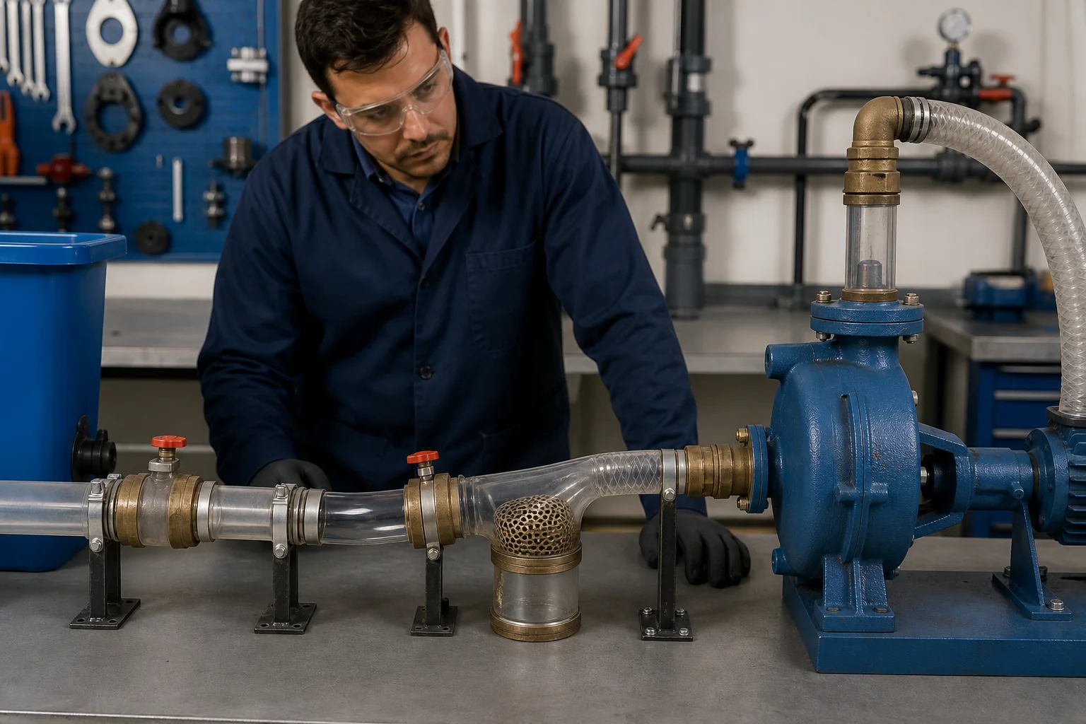
Check actual source level and pressure, vortexing, sediment, floating debris, ice, and intake submergence. Verify every suction valve position and confirm that a gate or internal disc has not detached. Inspect strainers, baskets, foot valves, temporary screens, reducers, gaskets, and flexible connectors. A hose can collapse under vacuum even when it looks normal while stopped; its liner may delaminate internally. Check for kinked routes, high points, unsupported weight, and undersized fittings. Differential pressure across a strainer is useful when taps are correctly located and gauges are reliable. Clean components through the approved method and capture removed material for root-cause review rather than washing away evidence.
Find air leaks and loss of prime
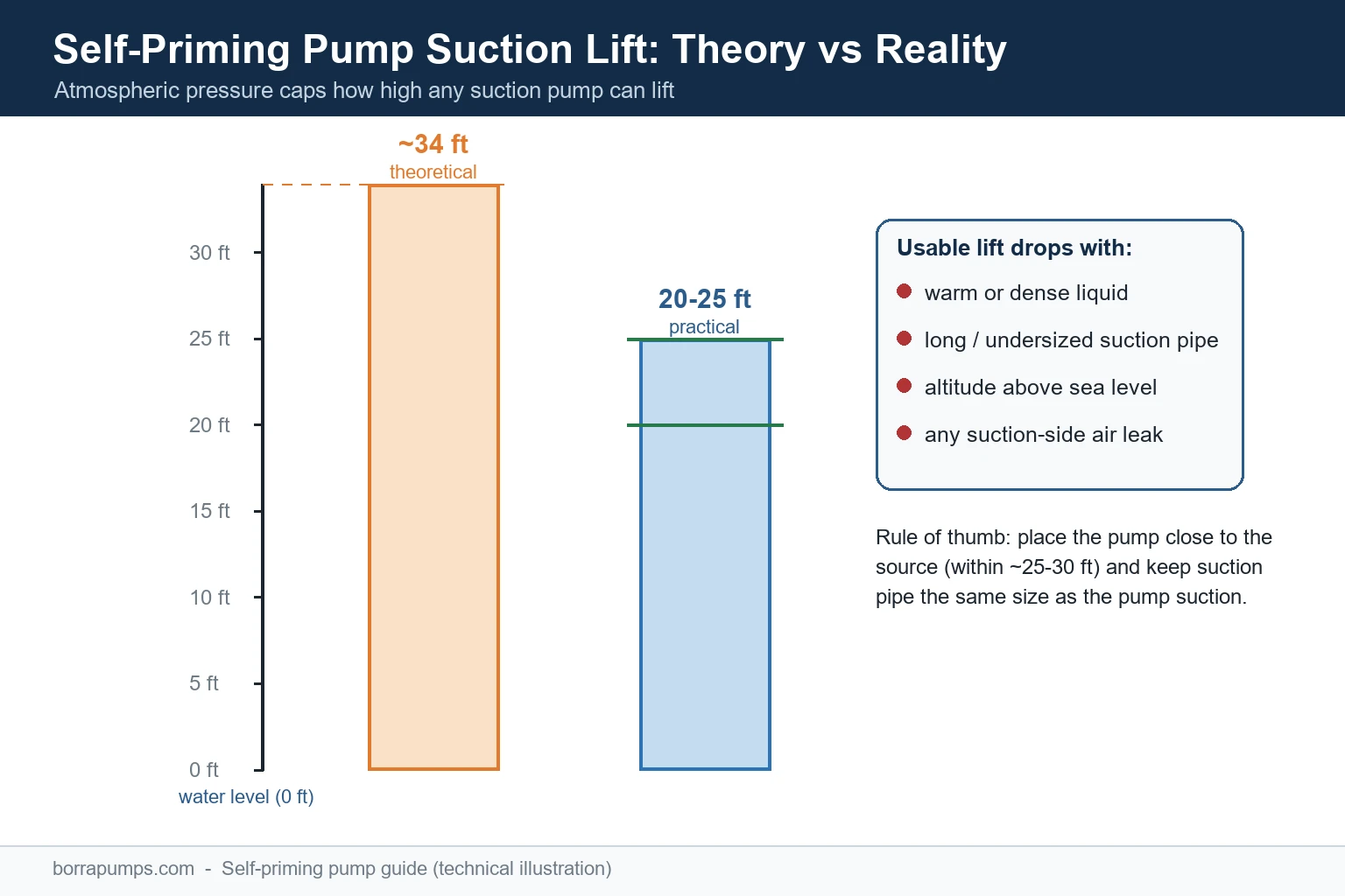
On suction lift systems, small air leaks can prevent prime without leaking liquid outward. Inspect flanges, gaskets, threaded joints, valve stems, instrument connections, drain plugs, casing seals, hose couplings, and the foot valve. Use only approved leak-testing methods suitable for the liquid and pressure; never apply unsafe pressure or flame. Confirm the pump casing and priming chamber are filled as required and that the priming system, ejector, vacuum pump, separator, and non-return devices operate correctly. On flooded suction, verify that the source valve is open and the line is vented where needed. Repeated loss of prime after shutdown can point to a leaking check or foot valve, trapped gas, or a suction route that drains back.
Projekt-Entscheidungstabelle
| Observed symptom | Possible suction-side cause | Verifizierung |
|---|---|---|
| Low flow with higher suction vacuum | Blocked strainer or pipe restriction | Compare suction pressure and inspect differential |
| Intermittent flow and bubbles | Air leak, vortex or low level | Check source, joints and submergence |
| Prime lost after shutdown | Foot/check valve leak or drain-back | Observe hold condition and approved leak test |
| Hose flattens during operation | Insufficient vacuum rating or failed liner | Inspect dynamically and replace correctly |
| Rapid repeat blockage | Upstream debris, ragging, scale or sediment | Identify removed material and entry path |
| Flow remains low after cleaning | Other system or pump fault | Check speed, rotation, discharge and wear |
Isolate and remove an internal blockage safely
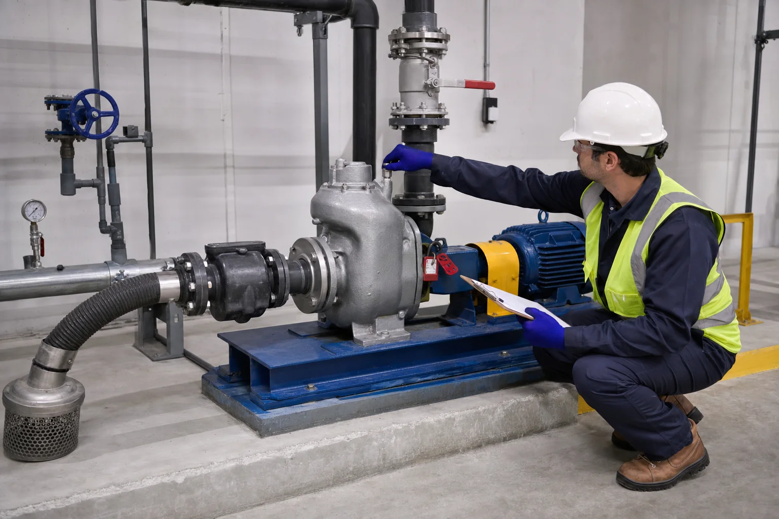
Review the safety data, temperature, pressure, biological hazard, confined-space risk, and environmental controls before opening the line. Stop the pump, isolate energy, close and secure valves, depressurize, drain to an approved location, verify zero energy, and provide containment. Heavy strainers and pipe sections need lifting plans. Use cleanout ports or removable spool pieces where designed rather than driving rods blindly through piping. Sharp debris, chemicals, and wastewater require appropriate tools and protective controls. After removal, inspect the material and its entry path. Ragging may need upstream screens or operating changes; scale may indicate chemistry or temperature; collapsed lining requires hose replacement; construction debris points to incomplete flushing. Restore gaskets, fasteners, supports, and valve positions under the approved procedure.
Prevent repeat blockages through system design
Match intake opening and strainer free area to the liquid and required flow. A finer screen reduces particle passage but can increase cleaning and suction loss. Provide accessible baskets, differential-pressure indication, duty/standby strainers, backwash, self-cleaning intake, or larger collection sumps where justified. Control velocity and avoid dead legs that collect solids. Keep the intake above settled sediment while maintaining submergence. For fibrous wastewater, select hydraulic passage and upstream handling together; a larger pump alone does not solve ragging. Include flushing and drain connections where they can be used safely. Operating procedures should define inspection triggers from pressure, flow, current, runtime, or level—not only a fixed calendar.
Recommission and verify the root cause is removed
Before restart, confirm all tools and debris are removed, covers and guards installed, valves positioned, vents and drains closed, piping supported, instruments restored, priming complete, and protection active. Start according to the pump procedure and observe suction pressure, discharge pressure, flow, speed, current, vibration, temperature, and leakage. Compare the readings with the original baseline and calculate whether the system operating point has returned. If the restriction recurs quickly, investigate the upstream process rather than repeating cleanout. Record the material, location, measurements before and after, photographs, maintenance action, and prevention recommendation. The goal is to restore hydraulic performance and remove the source, not simply to make the pump run for one shift.
Beschaffungs- und Abnahmeprotokoll
Ein vollständiger Lieferantenvergleich sollte ein einziges gemeinsames Datenblatt verwenden. Platzieren Sie die Auslegung und die alternativen Betriebspunkte, die Flüssigkeit, die Temperatur, Feststoffe, die Aufstellungshöhe, die Leistung, die Steuerung, die Installation, die Betriebsstunden, die Stückzahl, den Bestimmungsort und die erforderlichen Dokumente ganz oben. Bereinigen Sie Unterschiede im Lieferumfang, bevor Sie Preis oder Wirkungsgrad vergleichen. Fordern Sie eine zertifizierte Kennlinie oder Leistungsdaten, die Leistungsaufnahme, die Betriebsgrenzen, Werkstoffe, Abmessungen, das Gewicht, Anschlüsse, den Motor oder Antrieb, die Steuerung, Zubehör, Prüfungen, die Konservierung, Ersatzteile, die Installationsanleitung und die Gewährleistungsgrenze an. Dokumentieren Sie jede Abweichung und jede offene Annahme. Führen Sie während der technischen Prüfung jedes angebotene Merkmal auf eine Projektvorgabe zurück, anstatt Punkte für Merkmale zu vergeben, die der Betriebspunkt nicht benötigt. Messen Sie während der Inbetriebnahme dieselben Variablen, die für die Auswahl verwendet wurden, damit das installierte Ergebnis mit der ursprünglichen Grundlage verglichen werden kann. Wenn sich die Anlagenbedingungen vor Ort unterscheiden, aktualisieren Sie die Berechnung und holen Sie eine verantwortliche Genehmigung ein, bevor Sie Ausrüstung oder Schutzeinstellungen ändern.
Wie dieses Thema mit BORRAPUMP-Ausrüstung zusammenhängt
Dieser Leitfaden unterstützt die frühe Überprüfung der industrial pump maintenance clogged suction pipe Anwendungsroute. Es vergibt kein finales Modell und behauptet nicht, dass eine Standardkonfiguration für jedes Projekt passt. Senden Sie die Betriebspunkte, Flüssigkeitsdaten, Anlagenzeichnung, Stromversorgung, Steuerung, Stückzahl, den Bestimmungsort, die erforderlichen Zulassungen und den Inspektionsumfang, damit das vorgeschlagene Produkt anhand der tatsächlichen Betriebsbedingungen überprüft werden kann.
Verwandte BORRAPUMP-Engineering-Handbücher
- Fehlersuche bei selbstansaugenden Pumpen
- self-priming pump cavitation checks
- Fehlersuche bei Wasserpumpen
Maßgebliche Quellen und weiterführende Lernmaterialien
US-Energieministerium Pumpensysteme; OSHA-Kontrolle gefährlicher Energie; OSHA-Behälter (oder: umschlossene Räume nach OSHA / enge Räume gemäß OSHA). Diese Quellen bieten allgemeinen sicherheitstechnischen, umweltbezogenen oder ingenieurtechnischen Kontext. Die aktuell geltenden Vorschriften, Projektgenehmigungen und Geräteanweisungen bleiben maßgeblich.
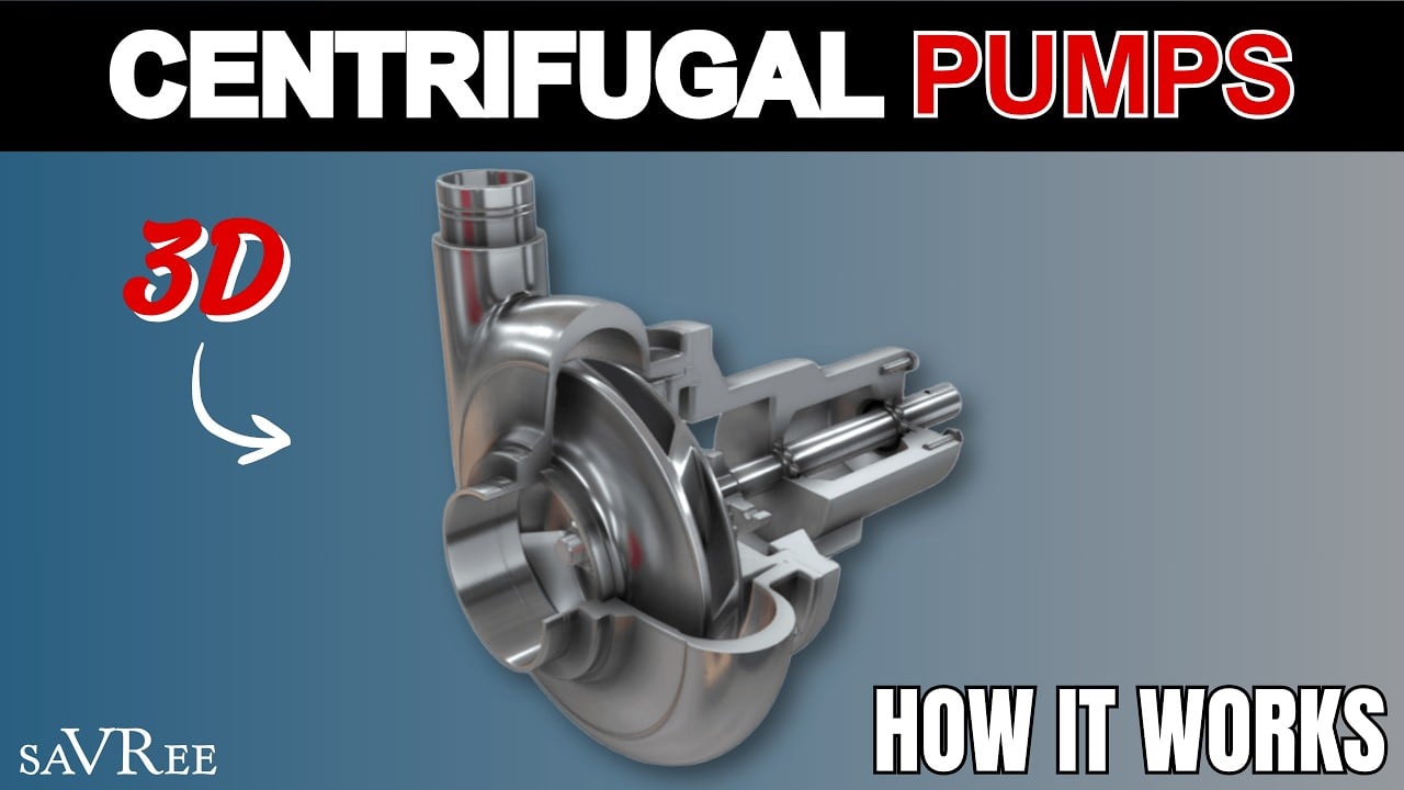
Lernvideo von saVRee: Wie Zentrifugalpumpen funktionieren. Es erklärt grundlegende Prinzipien und ersetzt keine projektspezifischen Anweisungen.
Häufig gestellte Fragen
Woranz erkenne ich, ob die Saugleitung verstopft ist?
Vergleichen Sie Volumenstrom, Saug- und Förderdruck, Stromstärke oder Leistung, Quellpegel und Basisdaten. Ähnliche Symptome können von Luft, Drehzahl, Drehsinn, Verschleiß oder druckseitiger Drosselung herrühren.
Kann ich ein verstopftes Saugrohr im angeschlossenen Zustand durchstoßen?
Nicht improvisieren. Isolieren, absperren, drucklos machen, entleeren, die Flüssigkeitsgefahr bewerten und die zugelassene Reinigungsmethode anwenden.
Warum zieht sich ein Saugschlauch nur im Betrieb zusammen?
Unterdruck steigt während des Betriebs an. Der Schlauch ist möglicherweise ungeeignet, weist einen Fehler im Innenfutter auf, hat Hitzeschäden oder eine übermäßige Verengung.
Wie verhindere ich, dass die Verstopfung zurückkehrt?
Identify the removed material and its source, then address intake design, screening, sump condition, velocity, cleaning access, process controls, and pump passage together.
Meilenstein für das Abschlussprojekt
Vor der Auftragserteilung oder einer Änderung vor Ort sind die genehmigten Betriebsdaten und Zeichnungen mit den Lieferantendaten, Materialien, Abmessungen, Gewichten, Anschlüssen, dem Antrieb, der Steuerung, dem Zubehör, dem Schutz, dem Prüfumfang, der Dokumentation, den Ersatzteilen, der Installationsmethode, dem Wartungszugang und den Bestimmungsortanforderungen abzugleichen. Verbleibende Annahmen sind zu dokumentieren und die Verantwortung für deren Klärung ist zuzuweisen. Die endgültig akzeptierte Information muss als Grundlage für Installation, Inbetriebsetzung und künftige Wartung dienen.